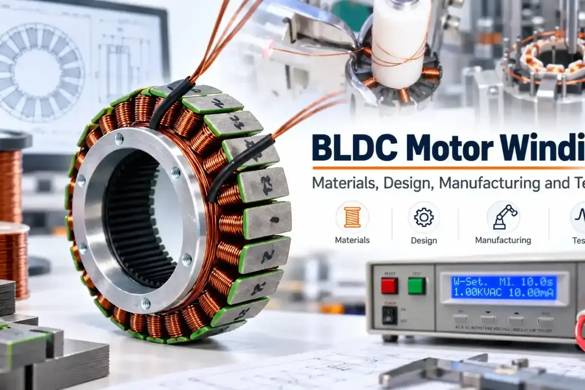
Introduction
BLDC motor testing is not limited to measuring speed, torque or efficiency.
A complete validation process should answer three questions:
Does the motor meet its design specification? → Can it deliver the required performance in the end-use application? → Can it survive the intended operating environment?
Depending on the project, testing may include dimensional inspection, electrical checks, functional and dynamometer testing, application-specific performance testing, thermal validation, vibration and shock, sealing, salt spray, EMC and endurance testing.
At Smart Drive, each test plan is defined around the project specification, end-use conditions and required acceptance criteria, rather than applying the same fixed test scope to every motor. Relevant IEC or ISO standards may be used as technical references where appropriate.
Our typical validation path is:
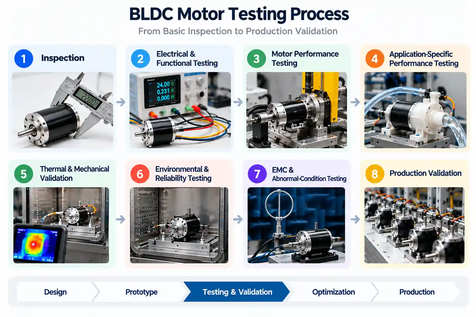
Design → Prototype → Inspection → Motor Performance Testing → Application Validation → Reliability Testing → Optimization → Production
For the development process before prototype validation, see our BLDC Motor Design Guide.
1. What Should BLDC Motor Testing Cover?
A complete BLDC motor validation plan may include several levels of testing.
| Test Category | Typical Checks |
|---|---|
| Visual & dimensional | Appearance, shaft, mounting dimensions, connectors, runout, critical tolerances |
| Electrical | Resistance, inductance, insulation, sensors, Back EMF |
| Functional | Startup, rotation direction, no-load speed and current |
| Motor performance | Torque, speed, current, power, efficiency |
| Application-level | Pump flow/head, fan airflow/pressure, propeller thrust, system efficiency |
| Thermal | Temperature rise, continuous operation, duty-cycle validation |
| Mechanical / NVH | Noise, vibration, balance, bearing condition |
| Environmental | High/low temperature, humidity, temperature cycling |
| Reliability | Drop, shock, external vibration, endurance, start-stop cycling |
| Sealing & corrosion | Leak test, IP protection, water ingress, salt spray |
| EMC | Emissions and immunity at drive-system or product level |
| Production validation | Repeatability, pilot production, end-of-line testing |
These tests serve different purposes.
Torque-speed testing verifies motor output. Application testing confirms whether the complete driven system achieves the required performance. Drop and shock testing evaluate mechanical robustness. Leak and IP testing evaluate environmental protection.
We do not apply every test to every motor. The test scope is selected according to the actual failure risks, operating environment and performance requirements of each project.
2. Visual, Dimensional and Electrical Inspection
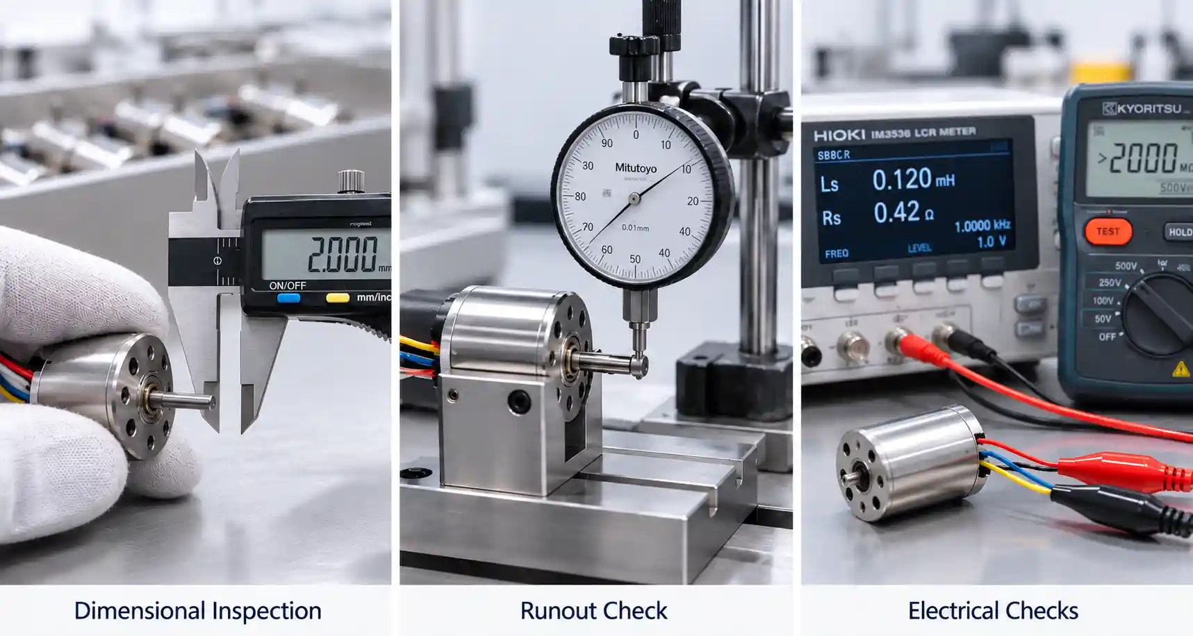
Performance testing should begin only after the motor has passed basic physical and electrical inspection.
Visual Inspection
Visual inspection identifies manufacturing or assembly defects before the motor is energized.
| External Condition | Assembly Condition | Connection & Identification |
|---|---|---|
| Housing surface | Bearing installation | Lead wires |
| Shaft surface | Rotor movement | Connectors |
| Visible damage | Fasteners | Cable outlets |
| Contamination | Covers and joints | Labels |
Inspection criteria are normally based on the released drawing, approved sample and project specification.
Dimensional Inspection
The finished motor should be checked against the approved drawing.
| Area | Typical Dimensions |
|---|---|
| Overall size | Diameter, total length |
| Shaft | Diameter, extension length, runout |
| Mounting | Hole position, PCD, flange, pilot diameter |
| Assembly | End play, concentricity, critical tolerances |
| Connection | Connector or cable outlet position |
For precision applications, small dimensional deviations can affect installation, shaft alignment, air gap, vibration and the interface with the driven equipment.
Basic Electrical Checks
Before complete motor testing, the following checks may be required.
| Electrical Check | Main Purpose |
|---|---|
| Phase resistance | Verify winding resistance and phase consistency |
| Inductance | Check winding and magnetic-circuit consistency |
| Insulation resistance | Check insulation between winding and core/housing |
| Hi-Pot | Verify dielectric withstand capability |
| Surge test | Detect turn-to-turn insulation weakness |
| Hall / encoder check | Confirm sensor operation and signal sequence |
| Phase sequence | Confirm correct phase relationship |
These stator-level tests are covered in more detail in our BLDC Motor Winding Guide.
For the function of the stator, rotor, bearings, housing and other major parts, see our BLDC Motor Components Guide.
3. Functional and Motor Performance Testing
After basic inspection, the motor can move into powered testing.
No-Load Test
No-load testing provides a quick indication of whether the assembled motor is operating normally.
| Parameter | What It Can Indicate |
|---|---|
| No-load speed | Basic speed capability and Kv consistency |
| No-load current | Mechanical and electromagnetic losses |
| DC bus voltage | Actual electrical test condition |
| Rotation direction | Correct phase and control configuration |
| Noise | Bearing, assembly or electromagnetic issues |
| Vibration | Rotor balance, bearing or structural condition |
If one prototype draws significantly higher current than another at the same voltage and speed, possible causes include bearing friction, rotor misalignment, air-gap variation, magnetic differences or assembly variation.
However, a motor that performs correctly at no load may still fail under load.
No-load testing is a basic health check, not complete performance validation.
Back EMF, Kv and Ke Verification
Back EMF testing helps confirm whether the electromagnetic characteristics of the physical motor match the design.
Back EMF is mainly influenced by:
Magnet Strength + Winding Turns + Winding Distribution + Rotor Geometry + Air Gap + Speed
| Measurement | Purpose |
|---|---|
| Back EMF amplitude | Compare actual electromagnetic output with the design |
| Phase-to-phase balance | Identify electrical or magnetic asymmetry |
| Waveform shape | Evaluate waveform consistency |
| Kv | Relate rotational speed to generated voltage |
| Ke | Relate generated voltage to rotational speed |
When comparing test data with simulation, the voltage definition must remain consistent. Line-to-line, phase, RMS and peak values should not be mixed.
If measured Back EMF differs significantly from the design value, possible causes include winding turns, magnet properties, magnet position, air-gap variation or differences in the actual magnetic circuit.
Torque-Speed Testing
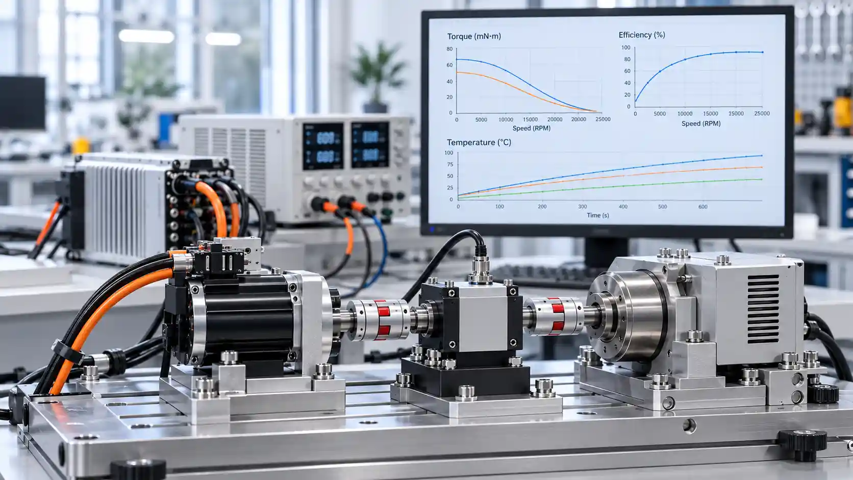
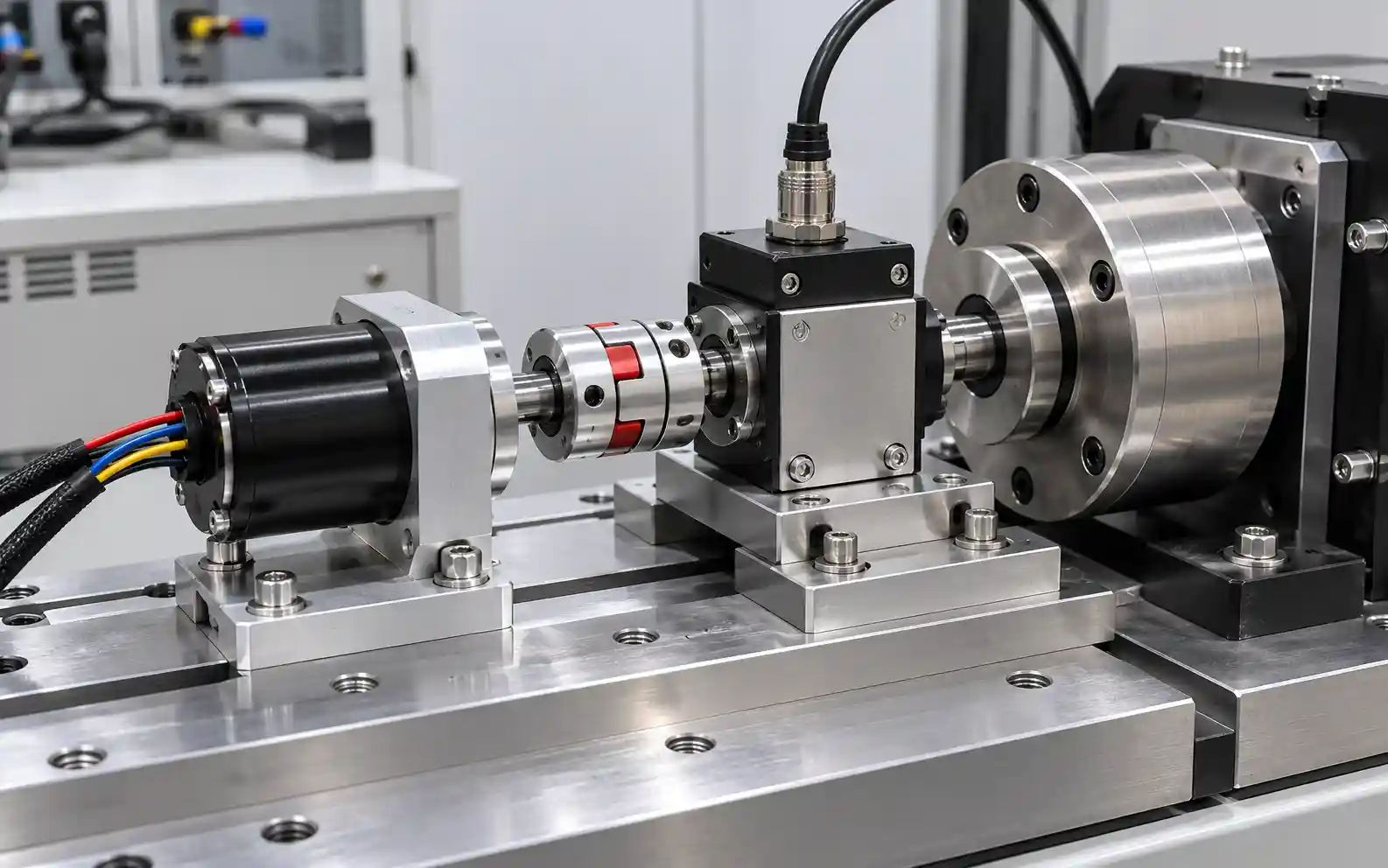
A dynamometer is commonly used to apply a controlled mechanical load while the motor operates at different points.
Typical setup:
Power Supply → Controller → BLDC Motor → Torque Sensor / Dynamometer
| Measured Parameter | Purpose |
|---|---|
| Torque | Mechanical output capability |
| Speed | Operating point |
| Voltage / current | Electrical demand |
| Input power | Electrical energy supplied |
| Output power | Mechanical shaft power |
| Efficiency | Energy conversion performance |
Mechanical output power is:
Pout = T × ω
When speed is measured in RPM:
Pout = T × 2π × RPM / 60
For example:
Torque = 1.5 N·m
Speed = 3,000 RPM
Mechanical output power is approximately:
471 W
This is why rated power alone does not fully define motor performance. A 500 W motor can produce the same power through very different torque-speed combinations.
Relevant sections of the IEC 60034 series can provide reference methods for rotating-machine performance and efficiency testing where appropriate. For custom BLDC motors, the actual test points and acceptance criteria are usually defined by the project specification.
Continuous Torque vs Peak Torque
| Continuous Torque | Peak Torque |
|---|---|
| Can be maintained under specified thermal conditions | Available only for a limited period |
| Mainly limited by steady-state temperature | Often limited by current, magnetic saturation and short-term heating |
| Important for continuous-duty applications | Important for acceleration or transient load |
| Must be defined with cooling and ambient conditions | Must be defined together with allowable duration |
For many applications, continuous torque is more meaningful than a high short-term peak torque value.
Efficiency Testing
Motor efficiency is calculated as:
Efficiency = Mechanical Output Power / Electrical Input Power × 100%
The measurement boundary must be clearly defined.
| Measurement Point | Result Represents |
|---|---|
| DC input of controller | Combined motor + controller efficiency |
| Motor electrical input | Motor-only efficiency when measured with suitable instrumentation |
If electrical power is measured at the DC input of the controller, the calculated result represents the complete motor-drive system.
Motor-only efficiency requires electrical input at the motor boundary and mechanical shaft output to be measured with suitable equipment. These two efficiency values should not be mixed.
For engineering evaluation, an efficiency map is usually more useful than a single maximum-efficiency value because efficiency changes with both speed and torque.
The more useful question is often:
What is the efficiency at the operating points where the application actually runs?
4. Application-Specific Performance Testing
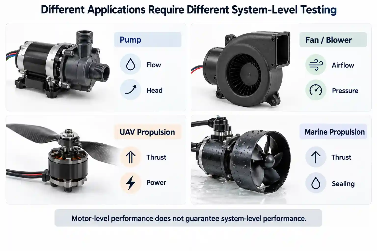
Motor-level performance does not guarantee system-level performance.
For many projects, the motor must also be tested together with the equipment it drives.
| Application | Additional System-Level Tests |
|---|---|
| Pump | Flow, head, Q-H curve, hydraulic efficiency, current, temperature |
| Fan / blower | Airflow, static pressure, airflow-pressure curve, efficiency, noise |
| UAV | Thrust, propeller RPM, current, power, thrust efficiency |
| Marine propulsion | Thrust, propeller RPM, system efficiency, sealing, continuous temperature |
| Gearmotor / robotics | Output torque, speed, backlash, positioning, dynamic response |
| Compressor | Pressure, flow, efficiency, current, temperature |
Pump Motor Testing
For a pump, torque-speed data alone is not enough.
Complete pump performance depends on:
Motor + Impeller + Pump Housing + Hydraulic Passage + Controller
Typical measurements include:
Flow Rate | Head | Q-H Curve | Motor Speed | Current | Input Power | Hydraulic Efficiency | Temperature
For rotodynamic pumps, standards such as ISO 9906 may provide a useful reference for hydraulic performance testing. Actual flow, head and acceptance targets are normally defined by the customer’s system requirements.
A motor may pass dynamometer testing while the complete pump still fails to achieve the required flow or head.
Fan and Blower Testing
A complete fan system may be evaluated using:
Airflow | Static Pressure | Speed | Power | Efficiency | Noise
The fan or impeller geometry and system resistance determine the actual operating point. Motor data alone cannot predict complete fan performance.
UAV Propulsion Testing
A UAV propulsion system should normally be evaluated as:
Motor + ESC + Propeller
Typical measurements include:
Thrust | Propeller RPM | Voltage | Current | Input Power | Motor Temperature | Thrust Efficiency
Useful relationships include:
Thrust vs Power
and
Thrust vs Current
The objective is to determine whether the complete propulsion system achieves the required thrust and efficiency at its actual operating points.
Marine and Kayak Propulsion Testing
For electric marine propulsion, system-level validation may include:
Propeller Thrust | Propeller RPM | Input Current | Input Power | System Efficiency | Motor Temperature | Continuous Operating Capability
Sealing, corrosion resistance and long-duration thermal performance are especially important for this type of application.
See our Custom Electric Kayak Motor Solution for an application example.
Robotics and Gearmotor Testing
When a BLDC motor is combined with a gearbox, encoder and controller, validation may include:
Output Torque | Output Speed | Backlash | Position Accuracy | Repeatability | Reversing Performance | Dynamic Response | Noise
The complete actuator should therefore be evaluated rather than only the bare motor.
Compressor Motor Testing
Typical system-level parameters may include:
Pressure | Flow Rate | Speed | Current | Input Power | Temperature | Efficiency
Again, the motor itself may meet its design target while the complete compressor does not.
5. Thermal, Noise and Mechanical Validation
A motor may achieve the required torque and speed yet still fail because of excessive temperature, vibration or mechanical instability.
Temperature Rise Test
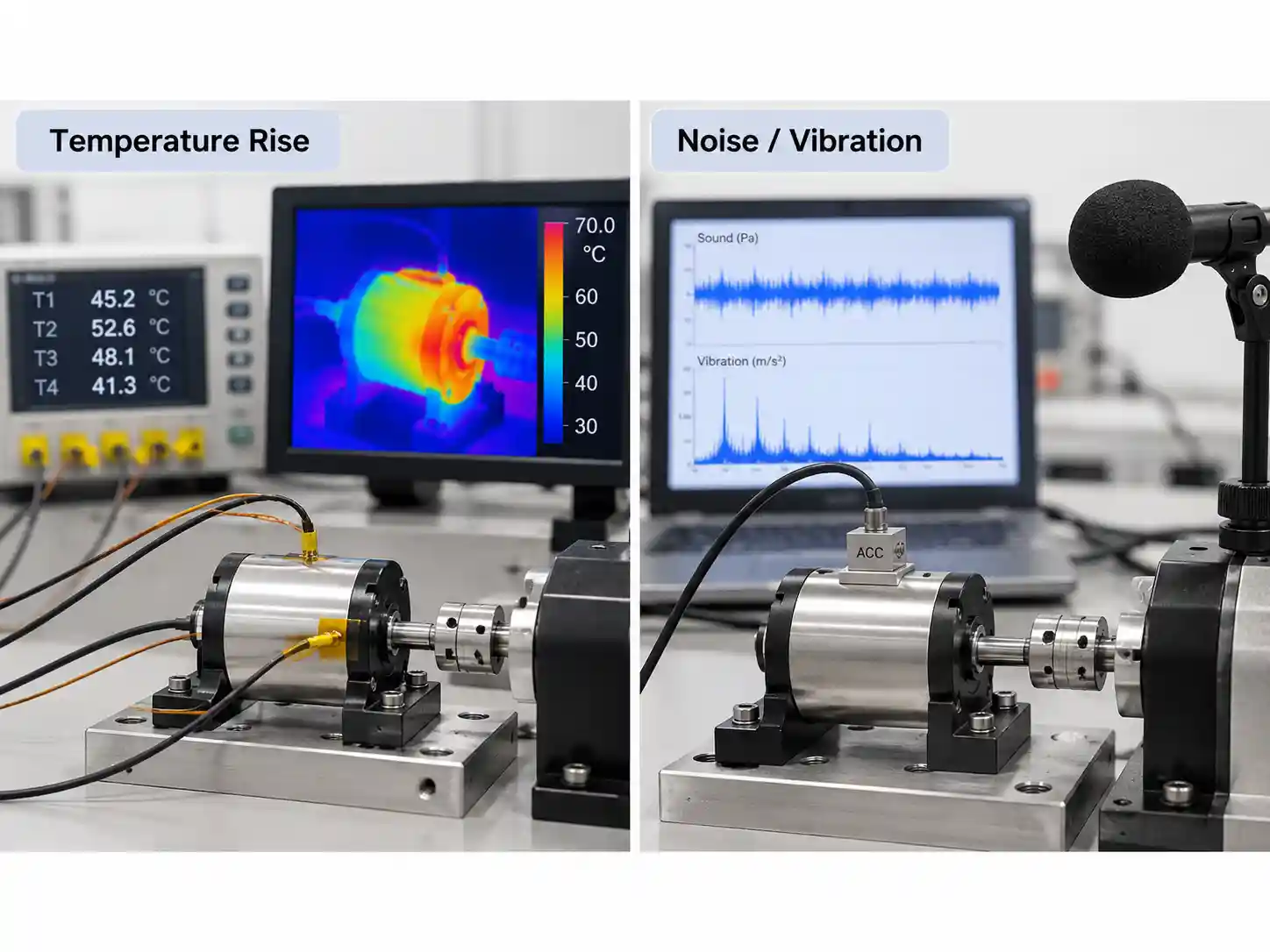
Typical monitoring locations include:
Winding | Housing | Bearing Area | Controller
A meaningful thermal result should record:
Ambient Temperature + Torque + Speed + Cooling Condition + Test Duration + Measured Temperature
| Main Loss | Typical Source |
|---|---|
| Copper loss | Winding resistance and current |
| Iron loss | Hysteresis and eddy-current loss |
| Mechanical loss | Bearings, seals and friction |
| Windage loss | Rotor movement through air |
| Controller loss | Switching and conduction loss |
For continuous-duty operation, the motor should normally be tested until temperature approaches thermal equilibrium.
For intermittent-duty operation, the actual duty cycle should be reproduced.
There is no single acceptable temperature limit for every BLDC motor. The allowable temperature depends on the winding insulation system, thermal class, magnet grade, bearings, lubricant, housing design and end-use environment.
Noise and Vibration
Motor noise and vibration can originate from both electromagnetic and mechanical sources.
| Electromagnetic Sources | Mechanical Sources |
|---|---|
| Cogging torque | Rotor imbalance |
| Torque ripple | Bearing condition |
| Electromagnetic excitation | Shaft misalignment |
| Controller commutation | Structural resonance |
| Current harmonics | Air-gap variation |
Noise should not automatically be treated as a mechanical defect.
Controller parameters may change motor noise even when the mechanical design remains unchanged. Conversely, controller tuning cannot correct a badly balanced rotor, damaged bearing or excessive runout.
For comparative testing, the same fixture, mounting method and operating condition should be used.
Mechanical Condition After Testing
After high-load or endurance testing, the motor may be rechecked for:
Shaft Runout | End Play | Bearing Condition | Abnormal Friction | Fastener Loosening | Mechanical Deformation
This helps determine whether any performance degradation originates from electrical, thermal or mechanical changes.
6. Environmental and Reliability Testing
Room-temperature performance does not prove that a motor can survive transportation or long-term operation in its intended environment.
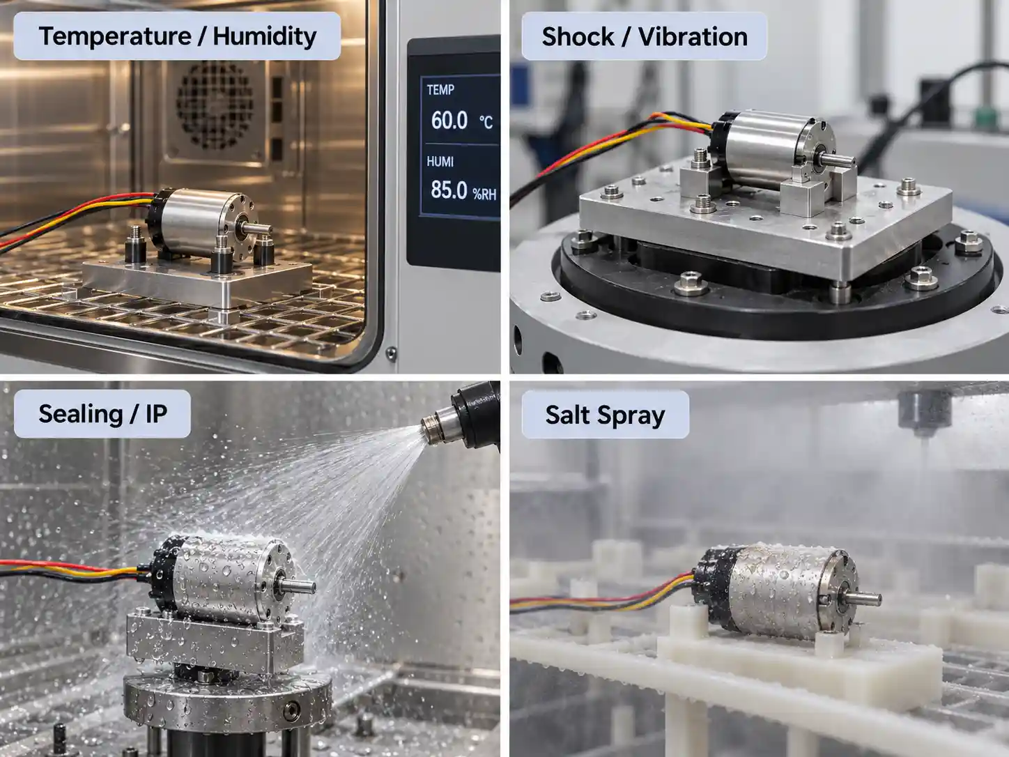
Test methods and severity should be selected according to the actual application. Where appropriate, the IEC 60068 series can provide useful reference methods for temperature, humidity, vibration, shock and related environmental testing.
Environmental Testing
| Test | What It Evaluates |
|---|---|
| High-temperature | Startup, insulation, magnets, bearings and material stability |
| Low-temperature | Startup, lubrication, materials and sensor behavior |
| Temperature cycling | Repeated thermal expansion and contraction |
| Thermal shock | Resistance to rapid temperature changes |
| Humidity | Insulation, corrosion, connectors, sensors and adhesives |
| Condensation exposure | Sealing and electrical reliability under moisture |
Mechanical Reliability Testing
| Test | Main Purpose |
|---|---|
| Drop test | Evaluate impact from handling, transportation or installation |
| Mechanical shock | Evaluate defined high-acceleration impact loads |
| External vibration | Simulate vibration from surrounding equipment or vehicles |
| Start-stop cycling | Evaluate repeated startup stress |
| Forward/reverse cycling | Evaluate repeated direction changes |
| Load cycling | Evaluate repeated torque changes |
| Speed cycling | Evaluate repeated speed changes |
| Endurance test | Evaluate long-term operating durability |
A drop test and a mechanical shock test are not the same.
Drop testing evaluates the effect of a physical fall or rough handling under defined conditions.
Mechanical shock testing applies a controlled acceleration pulse and is used to evaluate resistance to sudden impact loads.
External vibration testing is also different from measuring vibration generated by the motor itself. It evaluates whether the motor can survive vibration imposed by the surrounding machine, vehicle or equipment.
After these tests, the motor may be rechecked through:
Housing → Shaft → Bearings → Connectors → Fasteners → Electrical Function → Motor Performance
Endurance Testing
Running time alone is not a meaningful endurance specification.
A statement such as:
“Motor ran for 1,000 hours”
does not explain how severe the test was.
A useful endurance test should define:
Load + Speed + Voltage + Ambient Temperature + Cooling + Duty Cycle
Whenever possible, these conditions should reproduce the expected end-use operating profile.
7. Sealing, IP and Corrosion Testing
For pumps, marine motors, outdoor equipment and other exposed applications, environmental protection can be as important as motor efficiency.
Leak and Sealing Test
Critical sealing locations may include:
| Housing | Shaft | Electrical Interface |
|---|---|---|
| End-cover joints | Shaft seals | Cable outlets |
| O-rings | Bearing interfaces | Connectors |
| Cooling passages | Mechanical interfaces | Feed-throughs |
Common sealing-test methods include:
Pressure Decay | Vacuum Testing | Bubble Testing | Tracer Gas Testing
Pressure decay is often suitable for production testing because it provides a fast, non-destructive way to detect leakage.
IP Protection Testing
IP testing evaluates protection against solid-particle and water ingress.
The required protection level depends on the actual installation environment. IEC 60529 and IEC 60034-5 may be used as references where appropriate.
A motor installed inside protected equipment may require very different protection from a pump motor or marine propulsion motor exposed directly to water.
Leak testing and IP testing are related, but they are not equivalent.
A leak test checks the integrity of the sealing system under a defined pressure condition. Passing a leak test does not by itself demonstrate compliance with a required IP rating, which must be verified under the corresponding dust or water exposure conditions.
Salt Spray and Corrosion Testing
Salt spray testing may be relevant for:
Marine | Coastal | Outdoor | Agricultural | Mobility Applications
| Components Commonly Evaluated | Checks After Exposure |
|---|---|
| Housing | Surface corrosion |
| Shaft | Shaft and seal condition |
| Fasteners | Rust or coating failure |
| Connectors | Electrical contact condition |
| Coatings | Peeling, blistering or corrosion |
| Exposed metal parts | Continued motor operation |
Salt-mist methods from the IEC 60068 series may be used as references where appropriate, while exposure time and acceptance criteria should be defined by the project requirements.
Inspection should not stop at visible corrosion. Corrosion may also affect bearings, seals, electrical connections and long-term motor reliability.
8. EMC and Abnormal-Condition Testing
EMC Testing
Because BLDC motors are electronically commutated, EMC performance often depends on the complete drive system rather than on the motor alone.
Motor + Controller + Cable + Grounding + Shielding + Housing + Final Product Layout
can all influence the result.
| EMC Area | Typical Evaluation |
|---|---|
| Conducted emissions | Electrical noise transmitted through wiring |
| Radiated emissions | Electromagnetic energy radiated into the environment |
| Conducted immunity | Resistance to disturbances entering through cables |
| Radiated immunity | Resistance to external electromagnetic fields |
| ESD | Electrostatic discharge immunity |
| EFT / surge | Resistance to electrical transients |
For drive-system applications, standards such as IEC 61800-3 may provide useful reference requirements.
Final EMC requirements should still be defined according to the target market, product category and complete system configuration.
Abnormal-Condition Testing
Depending on the application, validation may also include:
| Condition | What Is Evaluated |
|---|---|
| Overload | Motor and controller response above normal load |
| Locked rotor / stall | Current, temperature and protection behavior |
| Overspeed | Mechanical and control margin |
| Overcurrent | Protection function |
| Sensor failure | Fault response |
| Phase loss | Drive protection |
| Cooling failure | Thermal protection |
| Controller fault | System-level protection behavior |
Some abnormal-condition tests may cause permanent motor damage.
For this reason, the test procedure, test duration, protection strategy and limit values should be defined before testing begins.
9. From Test Results to Final Validation
Testing is useful only when the measured data leads to an engineering decision.
| Test Result | Possible Causes to Investigate |
|---|---|
| Speed too low | Back EMF, voltage drop, controller limit, mechanical loss |
| Torque too low | Current limit, magnetic flux, air gap, controller setting |
| Current too high | Winding resistance, iron loss, bearing friction |
| Efficiency too low | Copper, iron, mechanical or controller loss |
| Temperature too high | Excess current, high losses, poor cooling |
| Vibration too high | Rotor balance, bearings, air gap, resonance |
| Back EMF abnormal | Winding, magnets, geometry, air-gap variation |
| Pump flow too low | Motor speed, impeller or hydraulic resistance |
| Fan airflow too low | Motor operating point, fan design or system pressure |
The correct response is not to change one motor parameter immediately.
For example:
High temperature does not automatically mean thicker winding wire is required.
The root cause may instead be excessive copper loss, iron loss, controller operation, insufficient cooling or mechanical friction.
Possible optimization areas include:
Winding → Stator → Magnets → Rotor → Air Gap → Laminations → Bearings → Cooling → Mechanical Tolerances → Controller
This creates the normal engineering loop:
Simulation → Prototype → Test → Compare → Optimize → Retest → Validate
If electromagnetic or mechanical redesign is required, see our BLDC Motor Design Service.
For physical prototype manufacturing and validation, see our BLDC Motor Prototyping Service.
After validation, the next objective is repeatability:
Validated Prototype → Pilot Production → Production Testing → Stable Manufacturing
Our BLDC Motor Manufacturing Service supports the transition from validated prototypes to low-volume and scalable production.
Frequently Asked Questions About BLDC Motor Testing
What tests are normally required for a BLDC motor?
There is no universal test list.
Most projects require dimensional, electrical, functional, performance and thermal testing. Environmental, sealing, EMC, shock, vibration, salt spray and endurance tests are added according to the application and project requirements.
Is dynamometer testing enough to validate a BLDC motor?
No.
Dynamometer testing verifies torque, speed, power and efficiency, but it does not fully evaluate application-level performance, sealing, environmental resistance or long-term reliability.
What is the difference between motor testing and application testing?
Motor testing evaluates the motor itself.
Application testing evaluates the complete driven system.
For example, a pump motor may pass torque-speed testing but still require flow and head testing after integration with the impeller and pump housing.
Does every BLDC motor need a drop test?
No.
Drop testing is application-dependent and is normally used when impact during handling, transportation, installation or operation is relevant.
Is a sealing test the same as an IP test?
No.
A sealing test checks leakage through joints, shaft seals or cable exits under defined conditions.
IP testing evaluates protection against specified solid-particle and water exposure. Passing a leak test does not automatically mean the motor will pass the required IP test.
Does every BLDC motor require salt spray testing?
No.
Salt spray testing is mainly relevant to marine, coastal, outdoor, agricultural and other corrosion-prone environments.
Does every project need to follow IEC or ISO standards?
No.
For most custom motor projects, the test plan is defined primarily by the project specification, end-use conditions and required acceptance criteria.
IEC, ISO or industry-specific standards may be used as technical references where appropriate, but the actual test scope and severity should be agreed for each project.
When should a BLDC motor be retested?
Retesting is generally required after changes to the winding, magnets, stator or rotor geometry, bearings, air gap, housing, sealing, cooling system, controller or manufacturing process when those changes may affect performance or reliability.
Conclusion
BLDC motor testing should not be limited to torque-speed or efficiency measurement.
A complete validation process may include:
Inspection → Electrical Testing → Functional Testing → Motor Performance Testing → Application Validation → Thermal & Mechanical Validation → Environmental & Reliability Testing → Sealing & EMC
The exact test scope should reflect the motor design, project requirements and actual operating environment.
The final objective is not simply to prove that the motor runs.
It is to confirm that:
the motor meets its specification, delivers the required performance in the end-use application and survives its intended operating environment.
At Smart Drive, we support the complete process from motor design and prototyping to testing, validation and production.
Need to Test or Validate a Custom BLDC Motor?
Share your voltage, torque, speed, motor dimensions, duty cycle, application requirements, drawings or existing test data.
Our engineering team can evaluate the project and recommend the appropriate testing and development path.