Introduction
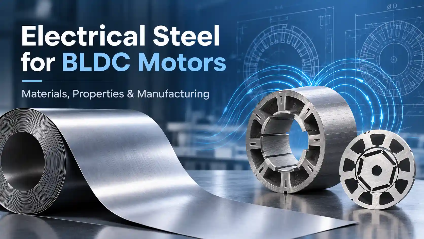
Choosing the right core material is an important part of BLDC motor design.
A motor may have sufficient copper, magnets, and mechanical strength, but still fail to achieve its efficiency, temperature, torque, or speed targets because the electrical steel is not properly selected.
The stator and rotor cores are not simply structural components. Their magnetic properties directly affect flux density, iron loss, efficiency, thermal performance, and power density.
At Smart Drive, I treat electrical steel selection as part of the electromagnetic and manufacturing design process. I consider motor speed, electrical frequency, magnetic loading, efficiency targets, core geometry, production volume, and manufacturing method before selecting a material.
I explain how electrical steel is selected for BLDC motors within the broader BLDC Motor Design Process, including material properties, prototype processing methods, and progressive die stamping for mass production.

1. What Is Electrical Steel?
Electrical steel is a specialized iron-based magnetic alloy designed to reduce energy losses when subjected to alternating magnetic fields.
Electrical steel is widely used for laminated stator and rotor cores. These cores are important parts of the overall BLDC motor structure.
The material is mainly based on iron with controlled amounts of silicon and other alloying elements.
Silicon increases electrical resistivity and helps reduce eddy-current losses.
Other elements, such as carbon, manganese and aluminum, can also influence magnetic properties, mechanical strength, grain structure and processing behavior.
The exact chemical composition varies by grade and manufacturer.
For motor designers, the important point is that chemical composition, crystal structure, sheet thickness, insulation coating and heat treatment work together to determine magnetic performance.
Electrical steel is normally supplied with an insulating coating.
When individual laminations are stacked together, this coating increases electrical resistance between adjacent sheets and helps reduce circulating eddy currents inside the core.
This is why selecting silicon steel for BLDC motors involves much more than simply choosing a nominal sheet thickness.
2. Electrical Steel Classification for BLDC Motor Cores
Electrical steel can be classified from several different perspectives.
Two classifications are particularly important:
- Manufacturing process
- Magnetic orientation
2.1 Classification by Rolling Process
Hot-Rolled Electrical Steel
It is an older manufacturing route and is now rarely selected for modern high-efficiency BLDC motor laminations because its dimensional accuracy, surface quality, and magnetic performance are generally less suitable for precision motor cores than modern cold-rolled electrical steel.
Cold-Rolled Electrical Steel
Cold-rolled electrical steel is produced through further rolling at lower temperature after hot rolling.
Compared with hot-rolled material, it generally offers:
- Better thickness accuracy
- Better surface quality
- More consistent magnetic properties
- Better suitability for thin motor laminations
For modern BLDC motors, cold-rolled electrical steel is the primary material category used for stator and rotor laminations.
2.2 Classification by Magnetic Grain Orientation: Non-Oriented and Grain-Oriented Electrical Steel
Cold-Rolled Non-Oriented Electrical Steel — Common Choice for BLDC Motors
Cold-rolled non-oriented electrical steel does not have the strong preferred magnetic direction of grain-oriented steel and therefore provides relatively balanced magnetic properties in different in-plane directions.
This makes it well suited to rotating electrical machines, where the magnetic flux direction changes throughout the stator and rotor core. For conventional BLDC motors, non-oriented electrical steel is therefore the most commonly used electrical steel category for stator and rotor laminations.
Cold-Rolled Grain-Oriented Electrical Steel — Generally Unsuitable for Conventional BLDC Motor Cores
Grain-oriented electrical steel is optimized for magnetic flux along the rolling direction and exhibits strong magnetic anisotropy. It is widely used in transformers and other applications where the magnetic flux follows a dominant direction.
For conventional BLDC motor stator and rotor laminations, it is generally not preferred because the magnetic flux direction varies throughout the magnetic circuit. Specialized motor structures may use grain-oriented material in selected regions, but it is not the standard choice for conventional BLDC motor cores.
2.3 Material Selection Conclusion

3. Electrical Steel Grade Nomenclature and Key Selection Properties
Electrical steel grade designations vary by manufacturer and standard. Taking Baosteel non-oriented electrical steel as an example, the grade code typically indicates information such as nominal sheet thickness, product series, and core-loss class.
The exact grade-code definition and core-loss test condition should be confirmed against the manufacturer’s current datasheet, especially for high-frequency or special-purpose grades.


Core loss becomes particularly important as motor electrical frequency increases.
It is commonly associated with hysteresis loss and eddy-current loss, although actual motor core losses can be more complicated because of harmonics, rotational magnetic fields, manufacturing stress and other factors.
Reducing lamination thickness and increasing electrical resistivity can help reduce eddy-current losses.
However, thinner material also increases:
- Material cost
- Stamping difficulty
- Handling requirements
- Tooling requirements
The correct material is therefore a balance between magnetic performance, mechanical requirements and manufacturing economics.
According to Baosteel‘s published electrical steel data, non-oriented grades are available in different thickness and core-loss classes, allowing motor designers to balance magnetic performance, frequency and manufacturing cost.

4. Common Electrical Steel Grades for BLDC Motor Applications
There is no single electrical steel grade that is suitable for every BLDC motor.
The appropriate grade depends on:
- Motor speed
- Electrical frequency
- Magnetic flux density
- Efficiency target
- Temperature rise
- Production cost
4.1 Cost-Sensitive General-Purpose BLDC Motors
Example Candidate Grade: B50A800
B50A800 is a 0.50 mm general-purpose non-oriented electrical steel commonly used in cost-sensitive motor applications. Compared with thinner 0.35 mm or 0.20 mm low-loss grades, it generally offers lower material and processing cost and easier stamping, but its core loss becomes less favorable as electrical frequency increases.
It is therefore a practical option for low-to-medium electrical-frequency BLDC motors such as fans, water pumps, and some power tools, where cost and manufacturability are more important than achieving the lowest possible iron loss.
4.2 Higher-Efficiency Industrial and Automotive BLDC Motors
Example Candidate Grade: B35A250
B35A250 is a 0.35 mm non-oriented electrical steel that can be considered where lower core loss is required compared with conventional 0.50 mm grades. It may be suitable for industrial, automotive, robotics, and other applications where efficiency and thermal performance are important.
4.3 High-Frequency / High-Speed BLDC Motors
Example Candidate Grade: B20AHV150
B20AHV150 is a 0.20 mm thin-gauge low-loss electrical steel designed for applications where electrical frequency and core loss become critical. Compared with conventional 0.35 mm or 0.50 mm laminations, the reduced sheet thickness helps limit eddy-current loss as operating frequency increases.
This makes it suitable for applications such as high-speed hair-dryer motors, vacuum motors, FPV propulsion motors, and high-speed spindle motors, where high rotational speed and/or higher pole count can produce high electrical frequency.
These are starting points rather than mandatory specifications.
For example, B50A800 can be a practical candidate for some compact power-tool BLDC motors, but the final grade should be verified against the motor’s actual flux density, electrical frequency, temperature and efficiency requirements.
5. Prototype Processing of Electrical Steel Laminations
During a new motor development project, investing in a progressive stamping die before the electromagnetic design is validated can create unnecessary tooling costs.
For this reason, prototype laminations require flexible processing methods.
Two commonly adopted process schemes are presented as follows.
Laser Cutting + Stacking + Laser Welding
The process is:
Electrical Steel Sheet → Laser Cutting → Lamination Stacking → Alignment Fixture → Laser Welding → Prototype Core
The individual laminations are accurately positioned using a dedicated fixture.
The stack is then compressed and aligned before welding.
Laser welding provides localized joining without requiring a stamping die.
This method is suitable for:
- Early prototypes
- Small quantities
- Complex geometries
- Rapid design changes
- Electromagnetic validation
Bonded Stacking + Wire EDM
The second method avoids welding.
Individual electrical steel laminations are first stacked and bonded together.
The bonded stack is then machined using wire EDM to produce the required final profile.
The process is:
Electrical Steel Sheet → Lamination Stacking → Bonding → Wire EDM → Prototype Core
This method is useful for:
- Low-volume prototypes
- Complex profiles
- Special rotor geometries
- Early engineering validation
Two mainstream prototyping routes are available for BLDC motor cores. These methods allow engineers to modify the core geometry without manufacturing a complete stamping die, reducing tooling risk during early motor development.
Laser Cutting + Stacking + Laser Welding can be used for many prototype core geometries and provides good mechanical integrity without production stamping tooling.
Bonded Stacking + Wire EDM avoids laser welding and therefore requires no welding allowance. It can also eliminate welding-related thermal distortion and provide high dimensional accuracy for suitable prototype geometries.
Laser-welded stacks may be preferred where higher mechanical stack strength is required, while a bonded stack can also be combined with laser welding where additional structural reinforcement is needed.
These prototype core manufacturing methods are particularly useful during custom motor development, where electromagnetic designs may still require several iterations. Our BLDC Motor Prototyping Service supports this transition from engineering design to physical motor validation.

6. Progressive Die Stamping for Mass Production
For medium- and high-volume BLDC motor production, progressive die stamping with in-die interlocking is a commonly used manufacturing route. The electrical steel strip is continuously fed into high-speed presses and sequentially goes through pilot hole piercing, interlock forming, slot punching, rotor blanking, stator blanking and scrap cutting.
When in-die interlocking is used, stacked cores can be formed directly during the stamping process. This technology provides good dimensional consistency and high production efficiency.
Nevertheless, progressive dies require long lead time and high tooling investment, making it uneconomical for prototype verification and small-batch trial production.
A typical process includes:
Electrical Steel Coil Feeding → Pilot & Slot Punching → Interlock Forming → Lamination Blanking & In-die Stacking → Scrap Discharge
The electrical steel is supplied as a coil and continuously fed through the progressive die.
Different operations are completed at different stations.
The final laminations are produced continuously with repeatable dimensions.
What Does Stamping Quality Affect?
Stamping accuracy directly affects:
- Slot dimensions
- Rotor geometry
- Air-gap consistency
- Lamination alignment
- Burr height
- Core dimensions
Poor punching conditions can produce excessive burrs and dimensional variation.
The electrical steel coating is also important because it provides insulation between laminations.
Therefore, material selection, tooling design and stamping parameters should be considered together rather than as independent manufacturing decisions.

7. How We Select Electrical Steel at Smart Drive
When I select Electrical Steel for BLDC Motors, I start with the motor’s actual operating requirements rather than selecting a grade from a catalog.
I normally evaluate:
- Motor speed
- Electrical frequency
- Torque requirement
- Magnetic flux density
- Efficiency target
- Temperature rise
- Motor size
- Production volume
- Prototype requirements
- Final manufacturing process
The application determines the priorities.
For a compact power-tool motor, I may evaluate a material such as B50A800 when its magnetic and thermal characteristics match the design target.
For a high-efficiency motor, I may evaluate lower-loss B35A grades.
For high-speed motors, thinner electrical steel becomes more attractive because reducing lamination thickness can help limit eddy-current loss.
For UAV motors, weight and power density become particularly important.
For industrial pumps, continuous operation and thermal stability may be more important than achieving the lowest possible material loss.
The material selection must therefore be connected directly to the electromagnetic design.
This is particularly important when working with a custom BLDC motor manufacturer, because material selection, electromagnetic design and manufacturing process need to be optimized as one system.
From Prototype to Production
The manufacturing method also changes as the project moves through development.
For a new motor design, we may first use:
Laser Cutting + Stacking + Laser Welding
or
Bonded Stacking + Wire EDM
to validate the electromagnetic design without investing in progressive tooling.
After the geometry is validated, we can evaluate:
Progressive Die Stamping + In-die Interlocking
for volume production.
This approach allows us to optimize not only the material grade, but also the complete path from prototype development to mass production.
We also provide custom sample services for brushless DC motor iron cores.
8. Examples of Major Electrical Steel Manufacturers in China
China has several major electrical steel producers with established non-oriented electrical steel product lines.
Baosteel publishes a broad range of non-oriented electrical steel grades, including B35A, B50A and B65A series, with published magnetic and mechanical data.
Shougang is another major producer with non-oriented electrical steel products for motors, appliances and new-energy drive systems.
For an OEM project, I do not select a material supplier based only on price.
I compare:
- Material grade
- Thickness
- Core-loss data
- Magnetic induction
- Coating
- Availability
- Punching performance
- Lot consistency
- Minimum order quantity
- Prototype supply capability
For a custom motor project, material availability can become just as important as nominal magnetic performance.
9. FAQ
Is electrical steel the same as silicon steel?
Silicon steel is a commonly used name for electrical steel because silicon is an important alloying element. In engineering documentation, electrical steel is the broader and more precise term.
Should BLDC motors use non-oriented electrical steel?
For conventional rotating BLDC motors, non-oriented electrical steel is generally the appropriate starting point because the magnetic flux changes direction during rotation.
Is thinner electrical steel always better?
No. Thinner laminations can reduce eddy-current loss, but they can also increase material and manufacturing costs.
Can we prototype motor cores without stamping dies?
Yes. Laser cutting, laser welding, bonded stacking and wire EDM can all be considered depending on the geometry, quantity and validation requirements.
When is progressive die stamping suitable?
Progressive die stamping becomes attractive when the motor design is stable and production volume justifies the tooling investment.
Conclusion
Electrical steel is a functional part of BLDC motor design, not simply a structural material.
Its thickness, magnetic properties, electrical resistivity, coating and processing method all influence motor performance.
At Smart Drive, we evaluate the material together with electromagnetic design, prototype processing and mass-production requirements.
This allows us to move from:
Material Selection → Prototype Core → Motor Testing → Progressive Stamping → Production
with fewer redesign risks.