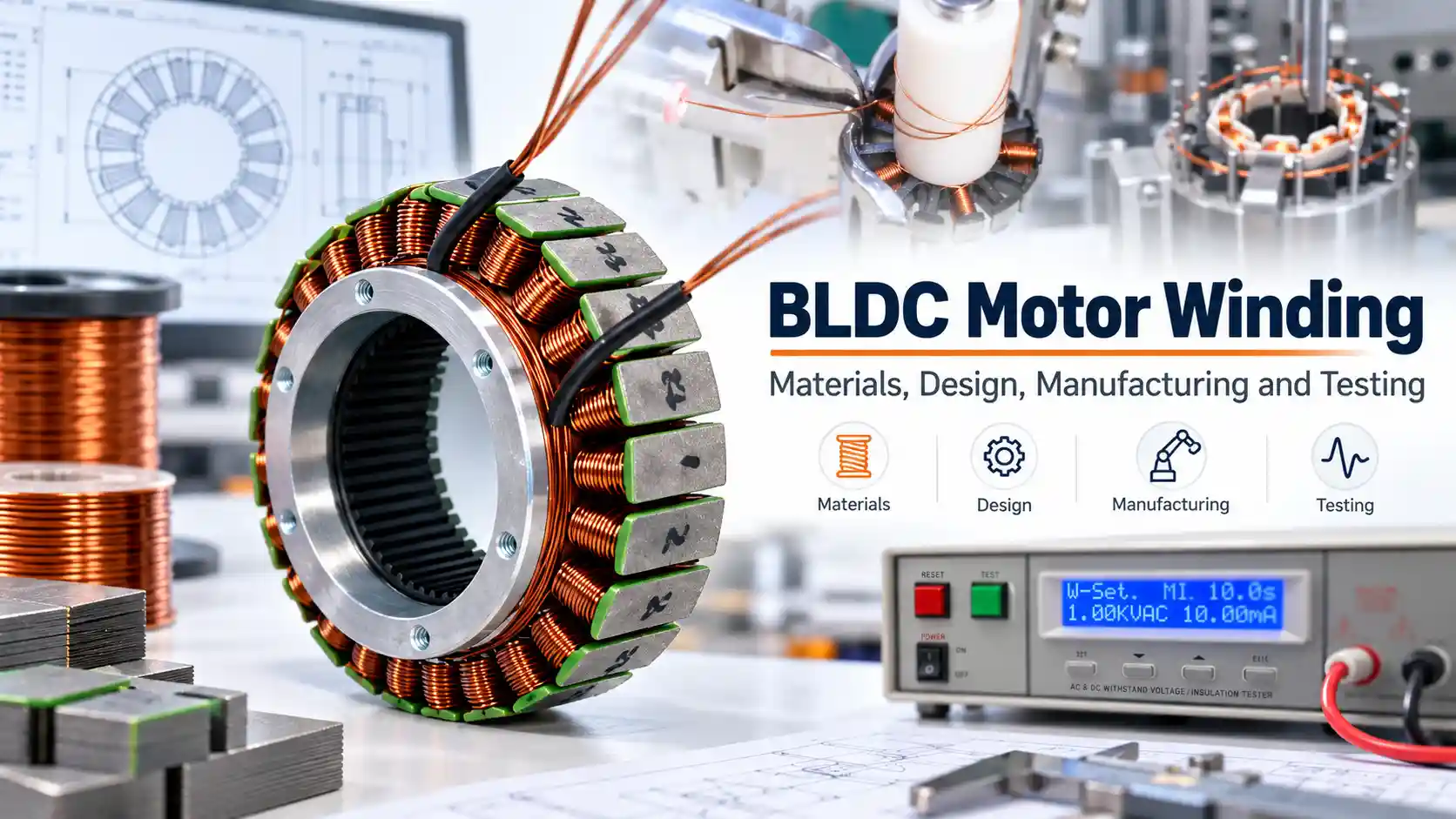
Introduction
The winding is one of the most important parts of a brushless DC motor.
Even when the stator core, permanent magnets and mechanical dimensions remain unchanged, different winding designs can significantly change motor speed, torque, current, efficiency and thermal performance.
Wire diameter, number of turns, winding layout, slot/pole combination, phase connection and manufacturing process all influence the final motor characteristics.
For this reason, BLDC motor winding is much more than placing copper wire into a stator. A practical design must consider the complete chain:
Material Selection → Electromagnetic Design → Manufacturing → Electrical Testing → Motor Validation
At Smart Drive, winding design is evaluated together with stator geometry, rotor pole number, operating voltage, target speed and torque, thermal requirements and future production methods.
This guide explains the materials, design parameters, manufacturing processes and inspection methods involved in BLDC stator winding, from prototype development to repeatable production.
For an overview of the complete motor structure, see our BLDC Motor Components Explained guide.
1. Understanding BLDC Motor Windings
What Is a BLDC Motor Winding?
In most permanent-magnet BLDC motors, the electrical winding is located on the stator.
When controlled three-phase current flows through the winding, it creates a rotating magnetic field. This field interacts with the permanent magnets on the rotor to produce electromagnetic torque.
The basic relationship is:
Stator Core → Insulation → Copper Winding → Rotating Magnetic Field → Permanent-Magnet Rotor
The winding directly affects three key areas:
Electromagnetic Performance: Speed constant (Kv), torque constant, and back EMF
Electrical Characteristics: Phase resistance, phase inductance, and current capability
Thermal & Efficiency Performance: Copper loss, temperature rise, and efficiency
Winding design therefore cannot be separated from the overall motor design.
Increasing the number of turns, for example, generally increases back EMF but also increases conductor length and required slot space. If the slot remains unchanged, more turns may require thinner wire, which increases resistance.
Similarly, thicker wire reduces resistance but occupies more slot area, while higher copper fill can improve electrical performance but make automatic winding more difficult.
In practice, winding design balances:
Electromagnetic Performance + Thermal Performance + Slot Space + Manufacturability
2. Materials Used in BLDC Motor Windings
2.1 Enameled Copper Wire
Enameled copper wire, also known as magnet wire, is the most commonly used conductor in BLDC motor windings.
Copper combines high electrical conductivity and current-carrying capability with compact conductor size, good winding flexibility, reliable termination, good thermal performance, and mature manufacturing availability.
Because stator slot space is limited, especially in compact or high-power-density motors, conductor efficiency is important.
Copper therefore remains the normal starting point for most custom BLDC motor winding designs at Smart Drive.
2.2 Copper, Aluminum and Other Conductors
Aluminum can also be used for motor windings.
Its main advantages are lower density and lower raw-material cost. However, aluminum has lower electrical conductivity than copper, so a larger conductor cross-section is normally required to achieve similar resistance.
This can become a disadvantage when stator slot space is limited.
Aluminum also requires additional attention to oxidation, electrical termination and process control.
Copper-clad aluminum, or CCA, combines an aluminum core with a copper outer layer and may be considered for specific cost or weight requirements.
Other conductive materials such as silver exist, but they are rarely practical for normal commercial BLDC motors because of cost.
For most industrial, robotics, appliance, power-tool and compact drive applications, enameled copper wire remains the mainstream solution.
2.3 Wire Diameter, Enamel and Thermal Class
Magnet wire selection should consider conductor size, finished diameter, film build and thermal class together with the electrical and manufacturing requirements of the motor.
Conductor Diameter. A larger conductor reduces resistance and increases current capability, but occupies more slot space and may limit the number of turns.
Larger Wire → Lower Resistance → More Slot Space → Fewer Possible Turns
Smaller wire allows more turns and easier routing through narrow slots, but increases resistance unless multiple strands are used in parallel.
Bare vs Finished Diameter. Wire size normally refers to the bare conductor diameter. The finished diameter includes the enamel coating and determines the actual space occupied in the slot, so it should be used when evaluating winding feasibility and slot fill.
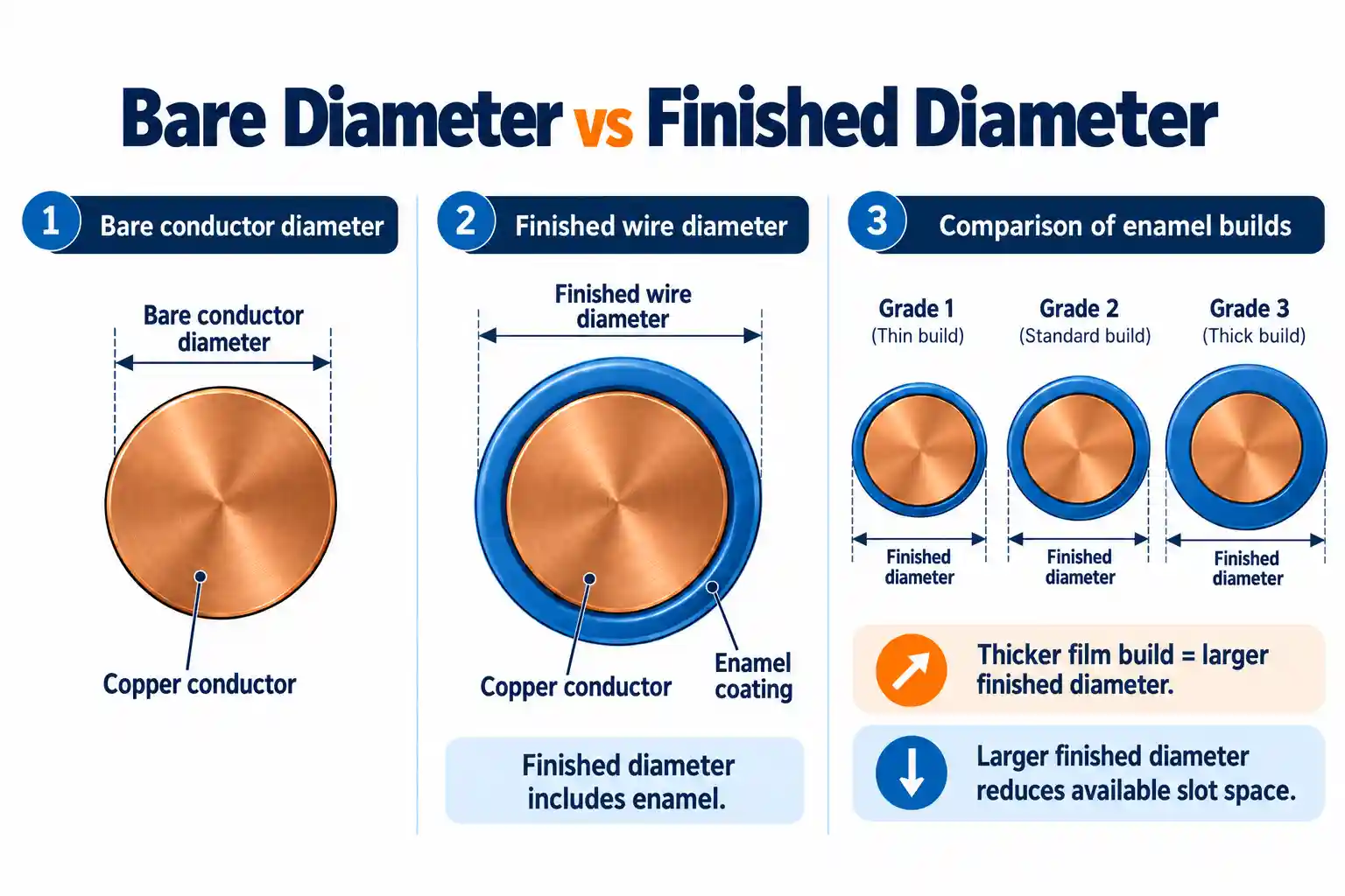
Enamel System, Thermal Class and Film Build
The enamel coating provides turn-to-turn insulation and mechanical protection. Thermal class applies to the insulation system and should not be determined from enamel chemistry alone.
Common thermal classes include:
Class B — 130°C
Class F — 155°C
Class H — 180°C
Class 200 (N) — 200°C
Class 220 (R) — 220°C
Film build is specified separately from thermal class. Depending on the wire specification, Grade 1, Grade 2 and sometimes Grade 3 may be available.
A thicker film improves insulation and mechanical protection but increases the finished diameter and reduces available copper space. For example, a 0.50 mm bare wire may have a finished diameter of approximately 0.54–0.59 mm, depending on the film build.
The wire specification should therefore confirm the bare diameter, finished diameter, film build and thermal rating.
Magnet wire is only one part of the insulation system. Enamel protects individual conductors, while slot insulation or bobbins separate the winding from the stator core.
For more detail, see our BLDC Stator Insulation guide.
2.4 Round Wire vs Flat Wire
Round wire is the most common choice for conventional BLDC motors because it offers good flexibility, wide size availability, mature winding technology, and compatibility with both manual and automatic winding. Multiple smaller wires can also be used as parallel strands when required.
Flat or rectangular wire can achieve higher copper utilization and lower resistance within a given slot, making it attractive for high-power-density designs. However, it requires tighter control of bending radius, conductor orientation, enamel protection, forming accuracy and winding equipment.
Flat wire is commonly seen in automotive traction motors, high-power-density PMSM/BLDC motors, and other applications where higher slot fill and current capability justify the additional manufacturing complexity. Hairpin windings are a well-known example of rectangular-conductor technology.
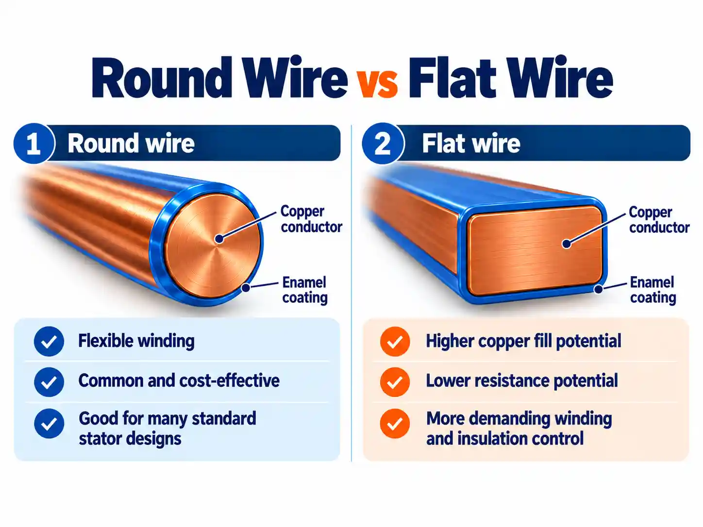
The correct choice depends on the motor architecture, slot geometry, electrical requirements and production process.
2.5 Supporting Winding Materials
A completed stator normally contains several additional materials. These may include:
- Plastic insulation bobbins
- Slot insulation paper
- Heat-resistant insulating sleeves
- Winding ties or lacing cord
- Impregnation varnish or resin
- Lead wires
- U/V/W phase terminals
- Heat-shrink tubing
- Soldered, welded or crimped connections
Impregnation can improve mechanical stability, vibration resistance, electrical insulation and thermal contact.
The available winding space itself is determined by the stator core geometry. For electrical-steel grades, lamination thickness, magnetic losses and stator/rotor core design, see our Electrical Steel for BLDC Motors guide.
3. BLDC Stator Winding Design
3.1 Winding Types and Slot/Pole Combinations
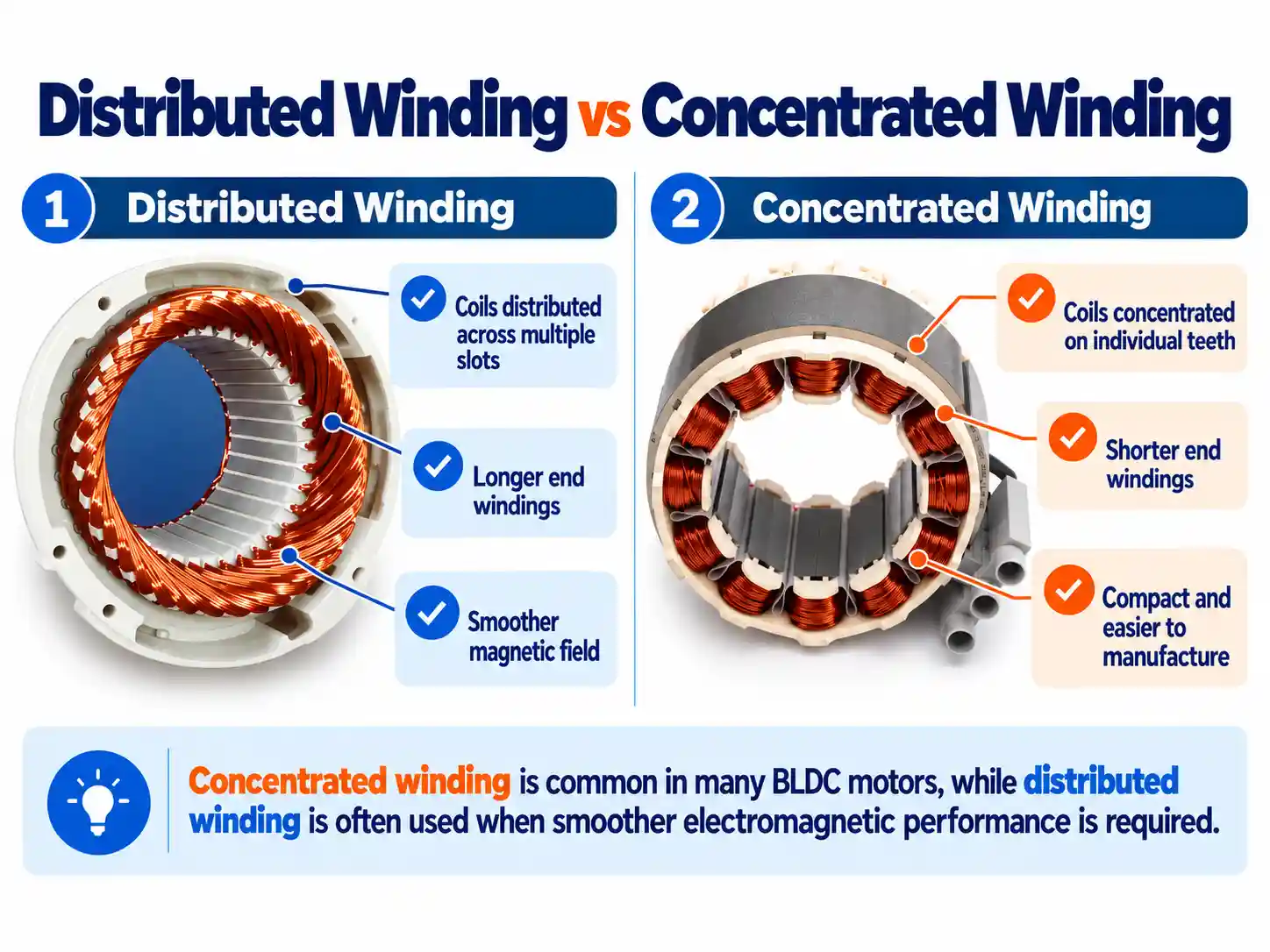
BLDC motor windings are mainly classified as distributed windings or concentrated windings, based on how the coils are arranged around the stator.
In a distributed winding, each phase is spread across several stator slots. This can produce a smoother magnetic field and lower harmonic content, but usually requires longer end windings and more inactive copper. Distributed windings are often used where smooth torque, low vibration or low acoustic noise is important.
In a concentrated winding, each coil is wound around one tooth or a small group of teeth. The shorter end windings reduce copper length and make the stator more compact and easier to manufacture. Concentrated windings are therefore widely used in compact BLDC and PMSM motors, although poor slot/pole selection can increase harmonics, torque ripple and acoustic noise.
The winding can also be classified by slots per pole per phase:
q = Q / (P × m)
where:
- Q = number of stator slots
- P = number of rotor poles
- m = number of phases
For a three-phase motor, m = 3.
If q is an integer, it is an integer-slot winding. If q is fractional, it is a fractional-slot winding.
A widely used combination in modern BLDC motors is the fractional-slot concentrated winding (FSCW). In other words, FSCW is not a separate classification from concentrated winding; it is a concentrated winding with a fractional q value.
Common three-phase BLDC/PMSM slot-pole combinations include:
| Slots | Poles | q | Common Design Tendency | Potential Trade-off |
|---|---|---|---|---|
| 6 | 4 | 0.50 | Simple winding | Higher harmonics |
| 6 | 8 | 0.25 | Compact structure | Higher electrical frequency |
| 9 | 8 | 0.375 | Good winding factor | Harmonic content |
| 9 | 10 | 0.30 | Good torque density | NVH sensitivity |
| 9 | 12 | 0.25 | Short end windings | Higher electrical frequency |
| 12 | 10 | 0.40 | Balanced performance | More winding steps |
| 12 | 14 | 0.286 | Good torque density | Radial-force harmonics |
| 18 | 16 | 0.375 | Smoother field | Higher complexity |
| 18 | 20 | 0.30 | Smooth torque | Higher complexity |
| 24 | 22 | 0.364 | Smooth operation | More complex manufacturing |
These are representative combinations rather than fixed recommendations; actual performance also depends on winding layout, motor geometry, magnetic design and control strategy.
FSCW is attractive because of its short end windings, compact construction, flexible slot/pole combinations and good manufacturability. It is commonly used in outer-rotor fans, UAV motors, robotics, power tools, appliances and other compact high-torque-density motors.
However, different slot/pole combinations produce different winding factors, harmonic content, cogging torque, electrical frequency and manufacturing characteristics. There is therefore no universally “best” combination.
At Smart Drive, the winding type and slot/pole combination are selected together according to the required speed, torque, noise performance, motor geometry and manufacturing method.
3.2 Phase Distribution and Winding Direction
For a common tooth-coil fractional-slot concentrated winding (FSCW), the coil pitch is typically y = 1. Each coil is wound around one stator tooth, with its two coil sides located in the adjacent slots.
The key question is therefore how each tooth coil is assigned to Phase A, B or C.
This can be determined from the electrical angle between adjacent teeth:
Electrical tooth pitch = (360° / Q) × p
where:
- Q = number of stator slots
- p = number of pole pairs
For example, in a 9-slot / 12-pole motor:
Mechanical tooth pitch = 360° / 9 = 40°
With 12 poles, the rotor has 6 pole pairs:
Electrical tooth pitch = 40° × 6 = 240°
Since 240° is equivalent to −120° within one electrical cycle, each adjacent tooth shifts by 120 electrical degrees in the reverse phase direction.
If Tooth 1 is assigned to Phase A, the phase sequence becomes:
T1 A → T2 C → T3 B → T4 A → T5 C → T6 B → T7 A → T8 C → T9 B
The phase groups are therefore:
Phase A: T1, T4, T7
Phase B: T3, T6, T9
Phase C: T2, T5, T8
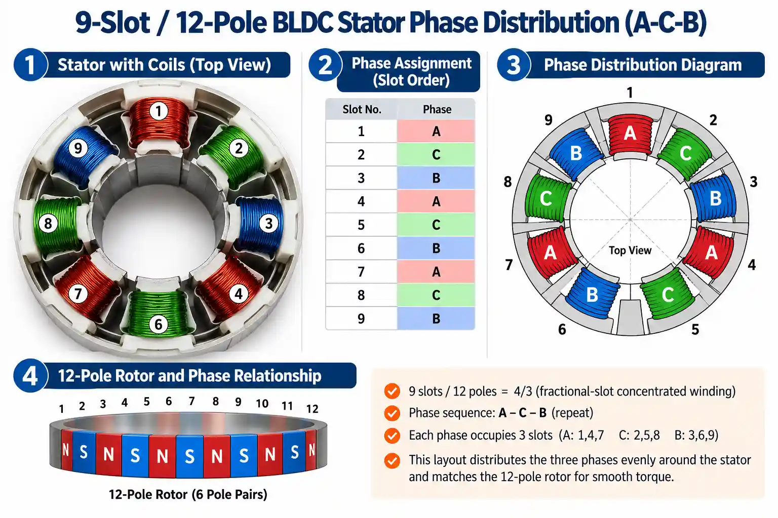
This shows why coils that are physically separated around the stator can still belong to the same electrical phase.
For FSCW, the winding layout can therefore be derived as:
Tooth Position → Electrical Angle → Phase Group
The winding direction and connection polarity are then selected so that the back EMFs generated by coils in the same phase add together rather than cancel each other.
Incorrect phase assignment or coil polarity can therefore distort back EMF and torque production even when the turn count is correct.
3.3 Star vs Delta Connection
After the three phase windings are formed, they can be connected in either Star (Y) or Delta (Δ).
In a Star connection, one end of all three phases is joined at a common neutral point. In a Delta connection, the end of each phase is connected to the start of the next phase, forming a closed loop.
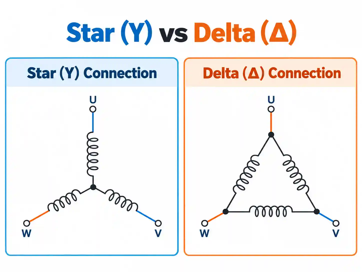
Basic Electrical Relationships
| Connection | Phase Voltage | Phase Current |
|---|---|---|
| Star (Y) | Vphase = Vline / √3 | Iphase = Iline |
| Delta (Δ) | Vphase = Vline | Iphase = Iline / √3 |
1. Equivalent Star and Delta Designs
If Star and Delta versions are designed for approximately the same voltage, speed, torque and shaft power, the winding must be changed accordingly.
| Parameter | Star | Delta |
|---|---|---|
| Turns | NY | ≈ √3 × NY |
| Conductor area | AY | ≈ AY / √3 |
| Phase current | IY | ≈ IY / √3 |
| Winding | Fewer turns, thicker wire | More turns, smaller wire |
The ampere-turns and copper utilization remain approximately equivalent. Therefore, neither connection is inherently more powerful when the winding is redesigned correctly.
2. Same Winding, Different Connection
If the same turns and wire size are retained and only the connection is changed:
| Parameter | Star → Delta |
|---|---|
| Kv | × √3 |
| Kt per line current | ÷ √3 |
| Line-to-line resistance | ÷ 3 |
Therefore:
Star → lower Kv, higher torque per line amp
Delta → higher Kv, higher voltage-limited speed
3. Selection Guidelines
| Priority | Preferred Connection |
|---|---|
| Controller line current is limited | Star — higher torque per line amp |
| Higher Kv from the same winding / DC bus | Delta — higher speed |
| Minimize circulating harmonic current | Star — no closed delta path |
| Thick wire is difficult to wind | Delta — smaller conductor |
| Reduce turns and winding time | Star — fewer turns |
| Avoid a separate neutral-point joint | Delta — no Star neutral joint |
| Two operating speed ranges | Y/Δ switching — Star low speed, Delta high speed |
The connection should therefore be selected according to Kv, controller current limit, wire size, winding manufacturability and harmonic behavior, rather than the simplified rule that “Star is for torque” and “Delta is for speed.”
3.4 Winding Specification and Design Verification
A complete winding design should define the winding specification and verify slot space, current density and motor output performance.
3.4.1 Winding Specification
Typical winding parameters include:
Number of phases · Turns per coil · Wire diameter · Coil pitch · Winding layers · Parallel strands · Parallel paths · Series/parallel connection · Star/Delta connection · Winding direction · Coil polarity · Slot/phase sequence · Winding development diagram
These parameters together define the complete stator winding.
3.4.2 Slot Fill Verification
The selected turns and conductor size must fit within the available slot area.
For round wire:
Acu = πd² / 4
Copper slot fill factor:
Kcu = Total Bare Copper Area / Slot Area × 100%
For n identical conductors in one slot:
Kcu = n × Acu / Aslot × 100%
Typical practical ranges for conventional round-wire windings are:
≤ 40% — comfortable production
40–45% — normal high-fill design
45–50% — high fill; winding simulation and prototype trial recommended
> 50% — difficult for conventional random winding
For manufacturability, the finished wire diameter and usable slot area after insulation should also be checked.
High-fill designs should be verified by winding simulation and prototype winding before release.
3.4.3 Current Density Verification
For continuous operation:
J = Iphase / Acu,total
With parallel paths and parallel strands:
Acu,total = a × ns × Acu
where:
- a = number of parallel paths
- ns = number of parallel strands
Typical continuous-duty design ranges are:
2–4 A/mm² — natural cooling
4–8 A/mm² — forced-air cooling
6–14 A/mm² — liquid cooling
> 14 A/mm² — enhanced or direct liquid cooling
These values are practical design ranges rather than fixed universal limits. Final continuous capability should be confirmed by thermal simulation and temperature-rise testing.
3.4.4 Motor Output Verification
The winding design must also allow the motor to meet its required output characteristics:
Back EMF / Ke / Kv · Rated Speed · Rated Torque · Torque-Speed Curve · Copper Loss
These results are checked by electromagnetic simulation and confirmed during prototype testing.
Winding Specification → Slot Fill → Current Density → Motor Output Verification
4. BLDC Motor Winding Manufacturing
A winding that works in electromagnetic simulation must also be physically manufacturable.
The winding process may change as a project moves from prototype development to volume production.
4.1 Prototype Winding
Manual winding is commonly used during early prototype development, especially when only a small number of motors are required.
Because it does not require dedicated winding tooling or machine setup, manual winding is well suited to the product prototype stage, allowing a small number of motors to be built and evaluated quickly.
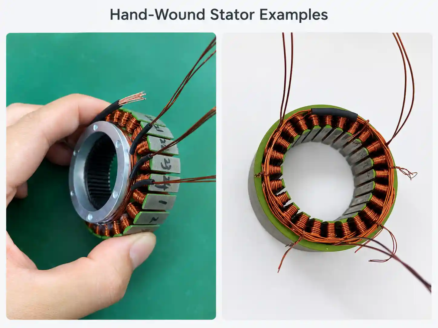
Prototype winding is used to verify:
- Actual slot capacity
- Turn count and wire size
- Winding sequence and coil placement
- End-winding height and lead routing
- Insulation and assembly clearance
- Manufacturability of the proposed winding
After assembly, the prototype motor is also tested for phase resistance, inductance, back EMF, speed, torque and temperature rise. These results confirm whether the selected winding specification meets the original electrical and performance targets.
Prototype winding is therefore not only a sample-building process, but also a fast method to validate both manufacturability and motor performance before production tooling and automatic winding parameters are finalized.
4.2 Automated Winding Methods
Once the motor design is validated, higher-volume production often moves to automated or semi-automated winding for improved repeatability and cycle time.
The winding method is selected mainly according to stator geometry, slot access and conductor arrangement.
Flyer Winding
Flyer winding is commonly used for stators with relatively open access around the teeth, especially many outer-rotor BLDC stators with outward-facing teeth.
The flyer guides the wire around each tooth while the stator is indexed between winding positions.
It is well suited to concentrated windings where the coil can be formed directly around the tooth with sufficient working space.
Needle Winding
Needle winding is used when the wire must be placed through restricted slot openings.
It is common for many inner-rotor stators with inward-facing slots and can also be used for compact outer-rotor designs with limited access.
The winding nozzle follows a programmed path through the slot while the stator is indexed between teeth.
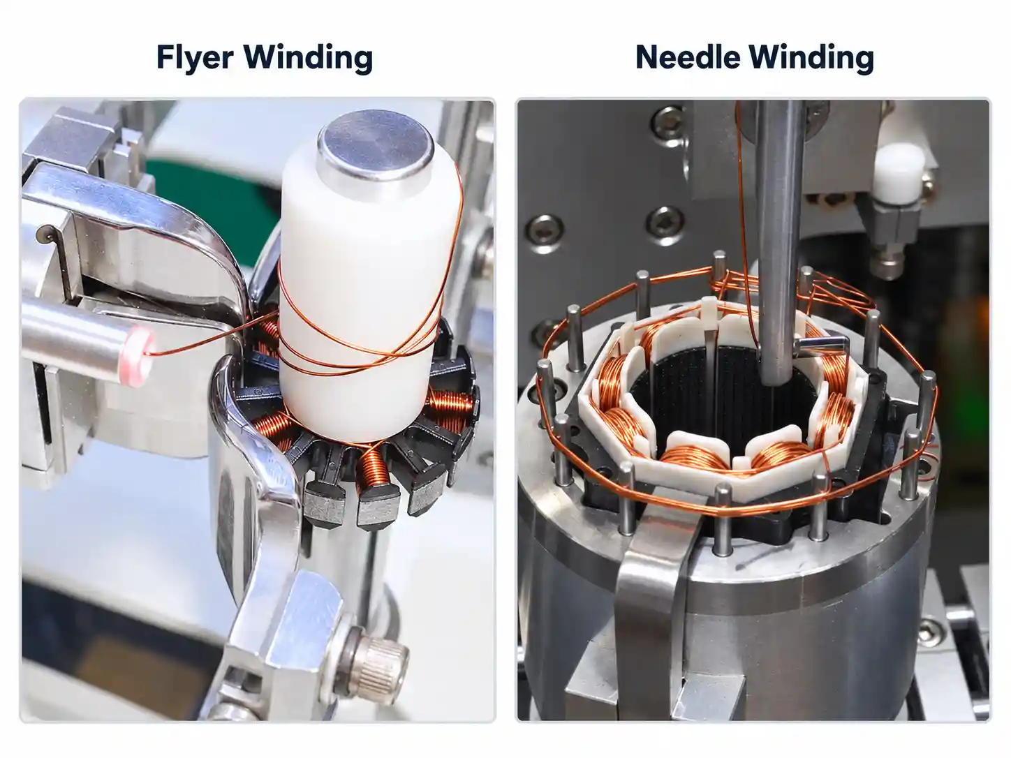
Compared with flyer winding, needle winding places greater requirements on nozzle size, slot clearance and positioning accuracy.
The selection between flyer and needle winding should therefore be based primarily on whether the winding path can access the tooth and slot geometry reliably without damaging the wire insulation.
4.3 Winding Tooling, Setup and Process Adjustment
Automatic winding requires dedicated tooling and a stable process window.
Typical production tooling may include:
- Stator fixtures
- Winding fixtures
- Wire guides
- Winding nozzles
- Coil-forming tools
- Indexing fixtures
- Lead-positioning tools
The winding nozzle or wire guide should match the wire diameter, parallel strand count, slot opening and winding path. Smooth, wear-resistant guide surfaces are important because excessive friction or sharp edges can damage the enamel.
The main setup parameters include:
- Turn count
- Winding direction
- Winding speed
- Wire tension
- Indexing angle
- Nozzle or guide position
- Traverse path
- Coil position
- Start-wire and finish-wire length
- Fixture position and stator concentricity
Winding speed is normally adjusted according to wire size, slot geometry and fill level rather than simply using the maximum machine speed.
A typical cycle may use:
Slow Start → Main Winding Speed → Slow Finish
Wire tension must also remain within a stable range.
Too low: loose or irregular coils
Too high: conductor stretch, enamel damage or insulation distortion
For needle winding, nozzle clearance and path accuracy are especially critical. For flyer winding, wire guiding and coil placement around the tooth require stable synchronization with stator indexing.
Final setup should confirm that:
Turn Count → Wire Placement → Coil Shape → Lead Position → Insulation Condition
remain consistent from one stator to the next.
The production winding process is considered stable only when the programmed parameters, tooling position and finished winding geometry are repeatable.
4.4 Termination, Forming and Post-Winding Processes
Winding is followed by additional operations such as:
Winding → Lead Preparation → Phase Connection → Soldering/Welding/Crimping → End-Winding Forming → Fixation → Impregnation or Potting (if required) → Curing (if applicable)
End windings may require forming or lacing to control their dimensions.
Lead wires and terminals must also remain clear of the rotor and surrounding mechanical components.
Impregnation varnish or resin can improve mechanical stability, vibration resistance, electrical insulation and thermal contact.
The selected material and curing conditions should remain compatible with the complete insulation system.
5. Winding Inspection and Electrical Testing
A finished winding should be inspected before final motor assembly.
Different tests identify different types of defects.
5.1 Visual and Dimensional Inspection
Visual inspection can identify:
- Damaged enamel
- Loose turns
- Crossed wires
- Excessive end-winding height
- Damaged insulation
- Incorrect lead routing
- Poor termination
This inspection should be completed before subsequent processes make winding defects more difficult to access or correct.
5.2 Electrical Consistency Testing
Resistance and inductance are basic checks for three-phase winding consistency. This test is typically performed on the completed stator before rotor assembly.
For a connected three-phase stator, measurements are normally compared between:
U–V, V–W and W–U
For windings that have not yet been finally connected, each phase circuit can be measured separately.
The imbalance is calculated as:
Imbalance (%) = (Maximum Value − Minimum Value) / Average Value × 100%
Note: Imbalance is defined here as (maximum value − minimum value) divided by the average of the three measured values. Other standards or customer specifications may use different calculation methods.
Typical production screening criteria are:
| Test Item | Imbalance | Assessment |
|---|---|---|
| Resistance | ≤ 2% | Typical screening target |
| > 2% | Investigate | |
| Inductance | ≤ 5% | Typical screening target |
| > 5% | Investigate |
Resistance imbalance may indicate:
- Incorrect turn count
- Poor electrical joints
- Connection errors
- Conductor damage
- Unequal conductor length or winding asymmetry
Because copper resistance varies with temperature, resistance measurements should be taken at a consistent winding temperature or corrected to the same reference temperature. For very low-resistance windings, a 4-wire Kelvin measurement is preferred.
Inductance should be measured using the same test frequency, excitation level, connection method and instrument settings for all three phases.
Abnormal inductance variation may indicate incorrect turns, connection errors, winding-position variation or stator magnetic-circuit inconsistency.
Resistance and inductance should be evaluated together when assessing three-phase winding consistency.
These limits are typical production screening criteria. Final acceptance criteria should be defined according to the motor design and agreed customer specification.
5.3 Insulation Testing
The winding must remain electrically isolated from the stator core and other conductive structures.
Insulation Resistance Test – Checks winding-to-core insulation resistance.
For stators with a rated winding voltage below 1,000 V, a typical production screening condition is:
500 VDC, ≥ 100 MΩ
This is a practical screening target for new, clean and dry stators. Insulation resistance is also affected by winding temperature and humidity.
Dielectric Withstand / Hi-Pot Test – Checks the dielectric strength between the winding and stator core.
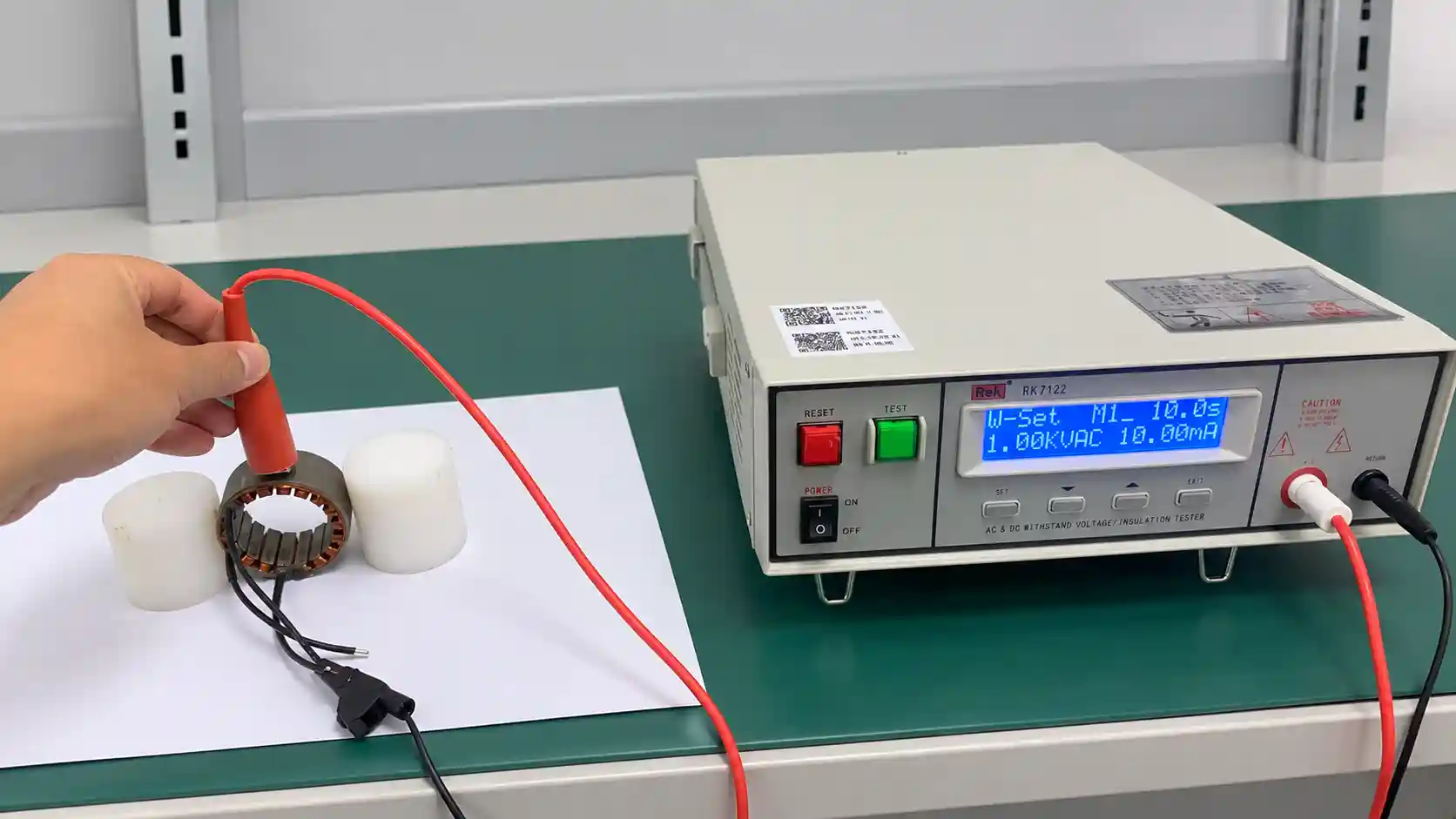
As a general IEC 60034-1 reference for new low-voltage windings:
- < 1 kW and rated voltage < 100 V: 500 V + 2U AC
- Other applicable low-voltage machines: 1,000 V + 2U AC, minimum 1,500 V
where U is the rated voltage.
A typical reference test duration is 60 seconds.
For converter-fed windings with specific insulation-system requirements, the final test voltage should follow the applicable motor and insulation standard rather than using these simplified reference values directly.
For small low-voltage stators, an internal production leakage-current limit, e.g., ≤ 5 mA, may be used as a screening reference. The actual limit should be validated according to winding capacitance, motor size and test conditions.
The test should show no breakdown, no flashover and no abnormal leakage current.
These tests mainly evaluate winding-to-core insulation and do not specifically detect turn-to-turn insulation defects.
Final test conditions and acceptance criteria should follow the motor design, applicable standard and agreed customer specification.
5.4 Turn-to-Turn and Enamel Integrity Testing
A winding can pass a Hi-Pot test while still containing weaknesses between adjacent turns.
Surge / Impulse Test – Commonly used to evaluate turn-to-turn insulation integrity by applying an impulse voltage to the winding and comparing the electrical response between phases, coils or a validated reference winding. Abnormal waveform differences may indicate turn-to-turn insulation weakness, incorrect turn count or winding inconsistency.
Typical evaluation is based on:
- Waveform shape and oscillation
- Phase-to-phase comparison
- Deviation from a validated reference waveform
For random-wound BLDC stators, surge-test voltage and acceptance criteria should be established according to the motor design, insulation system, winding configuration, test equipment and validated reference samples.
Pin-Hole Test (Salt-Water Method) – Used to evaluate the continuity of enamel insulation on magnet-wire specimens.
A wire specimen is immersed in a conductive solution and a test voltage is applied between the conductor and the solution. Electrical conduction indicates local pinholes or defects in the enamel coating.
Typical applications include:
- Incoming magnet-wire inspection
- Sample evaluation
- Failure analysis
IEC 60851-5:2026, Test 23 – Pin hole specifies the pin-hole test for winding wire.
This test is performed on magnet-wire specimens rather than completed stator windings. If winding-process damage is suspected, wire samples can be examined to determine whether tooling contact, stator burrs or handling have damaged the enamel.
5.5 Final Motor Performance Validation
After the winding passes stator-level inspection, the design must still be validated inside the complete motor.
Typical tests can include:
- Back EMF waveform and balance
- No-load current
- No-load speed
- Phase current
- Torque
- Efficiency
- Temperature rise
- Vibration
- Noise
The final objective is to confirm that:
Winding + Stator Core + Rotor Magnets + Controller + Mechanical Structure
work together as one motor system.
6. From Prototype Winding to Mass Production
The winding method used for a prototype is not always suitable for volume production.
A typical development route is:
Electromagnetic Design → Prototype Winding → Motor Testing → Winding Optimization → Production Tooling → Machine Setup → Pilot Production → Mass Production
Manual winding provides flexibility during early development, but once motor performance is validated, the winding must also be evaluated for production feasibility.
Key considerations include:
- Automated winding feasibility
- Cycle time
- Tooling and fixture design
- Wire handling and terminal connection
- Process repeatability
- Inspection and traceability
A winding may perform well electrically but still require modification if it cannot be produced consistently by automated equipment.
In such cases, slot geometry, bobbin structure, conductor selection or wire routing may be adjusted before production tooling is finalized.
At Smart Drive, manufacturability is therefore considered during motor development rather than treated as a separate step after prototype approval.
The goal is to convert a validated winding design into a production process that can be repeated consistently at scale.
Learn more about our custom BLDC motor development services.
Conclusion
BLDC motor winding directly influences motor resistance, back EMF, torque, speed, current capability and thermal performance.
These characteristics are determined by the combined effect of:
Wire Size → Turn Count → Winding Layout → Slot/Pole Combination → Connection Method → Insulation → Manufacturing Quality
Electrical design alone is not enough. The winding must also be practical to manufacture, properly insulated, correctly terminated and consistently verified.
A successful BLDC stator winding therefore depends on coordinated electrical, mechanical and manufacturing design.
At Smart Drive, winding development is treated as an integrated part of custom BLDC motor engineering, from electromagnetic design through prototype validation and production implementation.
Frequently Asked Questions About BLDC Motor Winding
What wire is normally used for BLDC motor windings?
Enameled copper wire is the most common choice because of its high electrical conductivity, compact size, winding flexibility and mature manufacturing process.
Aluminum and other conductors may be considered for specific cost or weight requirements.
Does thicker wire make a BLDC motor more powerful?
Not necessarily.
Thicker wire reduces resistance and increases current capability, but it also occupies more slot space.
Wire diameter must be selected together with turn count, operating voltage, current, stator geometry and target motor performance.
What is fractional-slot concentrated winding?
Fractional-slot concentrated winding, or FSCW, is a winding arrangement in which slots per pole per phase is fractional and the coils are generally concentrated around individual stator teeth.
It is widely used in many compact permanent-magnet motors because of its short end windings and manufacturing flexibility.
Is Star or Delta better for a BLDC motor?
Neither is universally better.
Star and Delta produce different voltage, current, Kv and torque-constant relationships.
The correct choice depends on operating voltage, target speed, turn count, wire size, torque requirements and controller limits.
Can prototype BLDC motors be wound manually?
Yes.
Manual winding is commonly used during early prototype development to verify turn count, wire size, slot capacity, winding route and assembly feasibility before dedicated automatic winding tooling is developed.
What tests are commonly used for BLDC stator windings?
Typical inspection can include visual inspection, phase resistance and inductance testing, insulation resistance, Hi-Pot testing and surge testing.
Magnet-wire specimen tests such as salt-water pinhole testing may also be used for incoming wire inspection or failure analysis when enamel defects are suspected.