Introduction
Selecting a standard BLDC motor is usually the fastest solution for a new product development project.
However, many OEM engineers eventually discover that catalog motors cannot fully satisfy their requirements.
The motor may have:
- Insufficient torque output
- Lower efficiency than expected
- Excessive noise
- High temperature rise
- Large installation size
- Short operating lifetime
- High overall system cost
The more effective approach is to develop a BLDC motor around the actual application requirements, including torque, speed, power, thermal conditions and mechanical constraints.
At Smart Drive, we help OEM engineering teams develop custom BLDC motors from initial concept evaluation to prototype testing and production.
This BLDC Motor Design Guide explains how engineers transform application requirements into a reliable production-ready motor solution.
| Requirement | Design Impact |
|---|---|
| Voltage | Determines winding configuration and controller compatibility |
| Torque | Influences magnetic design and current requirement |
| Speed | Affects pole selection and back EMF |
| Size limitation | Determines motor topology and thermal solution |
| Duty cycle | Affects thermal design and insulation class |
1. Why Custom BLDC Motor Development Is Required
Before starting a custom motor project, we first ask an important question:
Why is the existing motor solution not suitable?
In most cases, customers already have:
- An existing supplier motor
- A competitor product
- A previous generation design
- A standard catalog motor
The purpose of custom design is not simply to create another motor.
It is to solve a specific performance limitation.
Common customer challenges include:
1.1 Insufficient Speed or Torque
The existing motor may not achieve the required operating point.
Typical causes include:
- Limited electromagnetic capability
- Incorrect winding design
- Insufficient magnetic flux
- Poor torque-speed matching
The solution may require:
- Optimized winding parameters
- Different pole-slot combination
- Larger magnetic circuit
- Higher efficiency design
1.2 Excessive Temperature Rise
A motor may achieve the required output but generate too much heat.
Typical causes:
- High copper loss
- High iron loss
- Poor heat dissipation
- Insufficient motor size
Design improvements may include:
- Lower resistance winding
- Improved magnetic design
- Better thermal path
- Aluminum housing optimization
- Cooling structure improvement
1.3 Excessive Noise and Vibration
Noise problems are common in:
- Pumps
- Fans
- Household equipment
- Robotics
Possible causes include:
- Electromagnetic torque ripple
- Rotor imbalance
- Bearing selection
- Poor structural stiffness
Solutions may include:
- Optimized slot-pole combination
- Sinusoidal back EMF design
- Rotor balancing
- Mechanical reinforcement
1.4 Large Size or Excessive Weight
For applications such as:
- UAV
- Robotics
- Portable equipment
Motor size directly affects the final product.
Optimization may involve:
- Higher power density design
- Improved magnetic materials
- Structural redesign
1.5 High Cost
Sometimes the motor performance is acceptable, but manufacturing cost is too high.
Cost optimization may include:
- Material selection
- Manufacturing process improvement
- Component integration
- Simplified assembly design
A successful custom BLDC motor design should improve both performance and commercial value.
1.6 Application Example: Automotive Cooling Pump
An automotive cooling pump requires continuous operation at 6000 RPM with a constant torque of 0.5 N·m, and it must sustain stable long-term performance under an ambient temperature of 120°C. In contrast, a standard pump motor is only rated for a speed of 3000 RPM, a torque of 0.8 N·m, and a maximum operating ambient temperature of 60°C.
Due to the significant differences in operating parameters and environmental tolerance between the application requirements and standard motor specifications, targeted customized redesign is mandatory, covering the following core aspects:
- Optimization of motor windings, magnet structures, and slot-pole combinations
- Upgrading of mechanical component materials to enhance high-temperature resistance
- Selection and upgrade of high-temperature-resistant electronic components for motor controllers
- Redesign and optimization of the motor’s internal cooling and heat dissipation structure
2. Requirement Analysis and Application Definition
2.1 Application Requirements
The first stage of BLDC motor development is understanding the application.
We do not start by selecting components.
We start by defining:
Mechanical Requirements
Including:
- Required torque
- Operating speed
- Maximum speed
- Load characteristics
- Duty cycle
- Installation space
Electrical Requirements
Including:
- Voltage
- Current limitation
- Battery or power supply
- Communication interface
- Control requirements
Environmental Requirements
Including:
- Temperature range
- Water resistance
- Dust protection
- Vibration requirements
For example:
A water pump motor may require:
- Continuous operation
- Waterproof structure
- High reliability
A UAV motor may require:
- Lightweight design
- High efficiency
- High power density
Different applications lead to completely different motor solutions.
2.2 Existing Product Analysis
Before designing a new motor, we usually analyze the existing solution.
The evaluation includes:
- Motor structure
- Electrical parameters
- Performance curve
- Installation method
- Cost structure
We compare the current motor performance with customer requirements.
The design target becomes clear:
Example:
Existing motor:
- Torque: insufficient by 20%
- Temperature rise: too high
- Noise: unacceptable
Design objective:
- Increase torque output
- Reduce losses
- Improve acoustic performance
This step prevents unnecessary redesign.
3. Select the Correct BLDC Motor Architecture
3.1 Inner Rotor or Outer Rotor Design
Inner Rotor Motor
The rotor is located inside the stator.
Advantages:
- Higher speed capability
- Compact structure
- Better mechanical strength
Outer Rotor Motor
The rotor surrounds the stator.
Advantages:
- Higher torque density
- Large diameter magnetic structure
- Good low-speed performance
3.2 Integrated Gearbox or Direct Drive
For high torque and low speed applications, a gearbox may be required.
Examples:
- Robotic joints
- Electric actuators
Direct drive is preferred when:
- Low noise is required
- Maintenance must be minimized
3.3 Sensor or Sensorless Design
The control method depends on performance requirements.
Sensor-based systems provide:
- Accurate position feedback
- Better startup performance
Sensorless systems provide:
- Lower hardware cost
- Fewer sensors and wiring components
3.4 Integrated Controller or External Controller
Modern BLDC systems often integrate:
Power Stage
- MOSFET bridge
- Gate driver
- Current sensing
Control Unit
- MCU
- Communication interface
- Firmware
Protection Circuit
- Over current protection
- Over voltage protection
- Over temperature protection
3.5Thermal Design
Controller heat is usually transferred through:
- Aluminum housing
- Heat sink
- Thermal pad
- Potting material
| Design Decisions | Main Consideration |
|---|---|
| Rotor Structure | Inner rotor: higher speed and compact design. Outer rotor: higher torque density and low-speed performance. |
| Drive Configuration | Gearbox: high torque and low speed. Direct drive: lower noise and maintenance. |
| Sensor Configuration | Sensored: accurate feedback and startup performance. Sensorless: lower cost and simpler system. |
| Controller Integration | Integrated: compact solution. External: flexible system design. |
| Thermal Management | Housing, heat sink, thermal pad and potting materials affect heat dissipation. |
For example:
UAV Application
Requirement:
- High power density
- Lightweight
- Direct drive
Preferred:
Outer rotor BLDC motor
Pump Application
Requirement:
- High speed
- Compact size
- Waterproof
Preferred:
Inner rotor motor
Industrial collaborative robot joint
Requirement:
- High torque
- Precise positioning
- High dynamic‑response capability
Preferred:
Inner rotor + gearbox + encoder

4. Motor Design and Optimization
4.1 Preliminary Motor Concept Design
After defining the architecture, the next stage of the BLDC Motor Design Guide is motor concept development and optimization.
The preliminary design includes:
- Motor outline dimensions
- Mounting structure
- Shaft interface
- Electrical connector
- Communication interface
- Cooling method
At this stage, we confirm:
- Installation space
- Mechanical interface
- System integration requirements
The preliminary model allows customers to verify:
- Product compatibility
- Assembly method
- Size limitations
4.2 Electromagnetic Design
During BLDC motor development, electromagnetic optimization is one of the most important engineering stages.
We perform simulation analysis to optimize:
Stator Design
Including:
- Slot number
- Lamination size
- Winding arrangement
- Wire specification
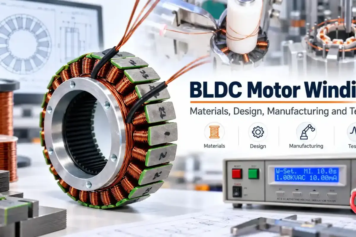
Winding arrangement and wire specification are then optimized according to voltage, current and torque requirements. Learn more in our BLDC Motor Winding Guide.
Rotor Design
Including:
- Magnet grade
- Magnet thickness
- Pole configuration
- Magnetic circuit
Performance Analysis
Simulation results normally include:
- Rated torque
- Peak torque
- Back EMF waveform
- Cogging torque
- Torque ripple
- Efficiency map
Thermal simulation evaluates:
- Copper loss
- Iron loss
- Temperature rise
The design is repeatedly optimized until performance targets are achieved.
| Parameter | Evaluation Focus |
|---|---|
| Torque ripple | Smooth operation and vibration performance |
| Efficiency | Energy loss and thermal performance |
| Temperature rise | Thermal reliability under rated load |
| Insulation class | Electrical safety and operating temperature |
| Air gap | Magnetic performance and manufacturing tolerance |

4.3 Mechanical Design
After electromagnetic optimization, we finalize the mechanical layout of the BLDC Motor Structure.
The detailed design includes:
Rotor Assembly
Including:
- Shaft
- Rotor core
- Magnets
- Balance structure
Stator Assembly
Including:
- Core
- Insulation structure
- Windings
- Terminal connection
Housing Structure
Including:
- Bearing installation
- Fastening method
- Heat dissipation
Special Designs
Depending on application:
- Waterproof sealing
- Cooling structure
- Gear mechanism
- Integrated actuator
- Controller mounting
All components must satisfy:
- Assembly requirements
- Manufacturing tolerance
- Reliability requirements
5. Prototype Development and Validation
5.1 Prototype Manufacturing
After completing 3D design, we generate production drawings.
Engineering drawings define:
- Material requirements
- Dimensions
- Tolerances
- Surface treatment
- Assembly requirements
Prototype validation is a critical stage in the BLDC Motor Design Guide because simulation results must be verified through physical testing of the Custom BLDC Motor Prototype.
Prototype manufacturing includes:
- Machined parts
- Molded components
- Winding process
- Motor assembly
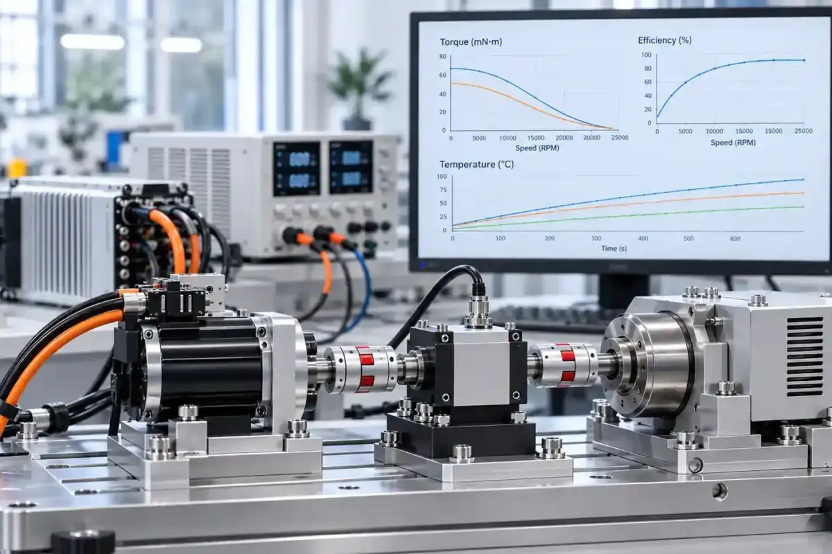
5.2 Prototype Testing
Prototype testing validates the design.
Typical tests include:
Performance Testing
- Speed
- Torque
- Efficiency
- Power output
Thermal Testing
- Temperature rise
- Continuous operation
Reliability Testing
- Noise
- Vibration
- Lifetime evaluation
If testing results do not meet requirements, we return to the design stage.
The development process is iterative:
Design →Prototype →Test →Optimization →Validation
6. Transition to Production
After prototype approval, the motor enters production preparation.
We optimize:
- Manufacturing process
- Assembly fixtures
- Quality control
- Supply chain
Smart Drive supports:
- Prototype production
- Low-volume manufacturing
- OEM production
Conclusion
A successful BLDC motor is not created by selecting components randomly.
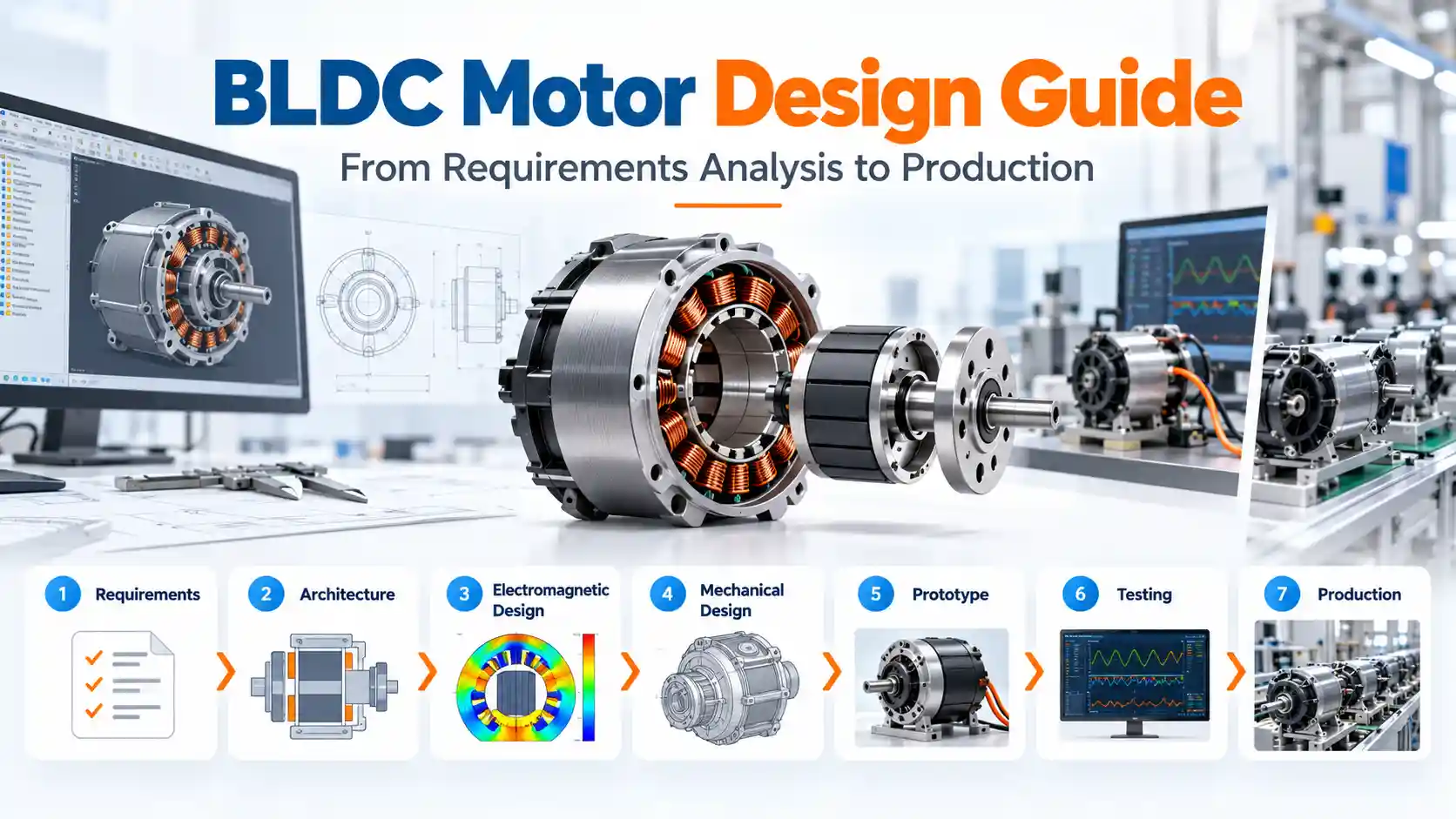
It requires a structured engineering process:
Application analysis →
Architecture selection →
Electromagnetic optimization →
Mechanical design →
Prototype testing →
Production validation
Through a complete BLDC motor design and development process, OEM companies can achieve higher performance, better reliability, and faster product development.
Frequently Asked Questions About BLDC Motor Design
This BLDC Motor Design Guide covers the complete journey from initial requirements to production validation.
1. How long does a custom BLDC motor design take?
Typical development:
0.5-2 months depending on complexity.
2. Can you modify an existing BLDC motor design?
Yes.
Common modifications include:
- Torque increase
- Speed adjustment
- Size reduction
- Thermal improvement
3. When should OEM companies choose custom BLDC motor design?
When standard motors cannot meet:
- Performance
- Size
- Cost
- Reliability requirements