Introduction
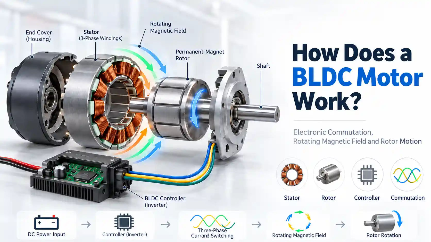
A BLDC motor works by using electronic commutation to replace the mechanical brushes used in traditional DC motors. The controller switches current between stator phases according to rotor position feedback, generating a rotating magnetic field that drives the permanent magnet rotor.
Although the BLDC motor working principle appears straightforward, a BLDC motor is actually an integrated electromechanical system consisting of a mechanical structure, an electromagnetic energy conversion system, and an electronic drive controller. These three elements work together to convert electrical energy into continuous rotational motion.
Understanding how a BLDC motor works is essential when selecting a motor, evaluating performance, or developing a custom BLDC motor solution.
Many engineers ask:
How Does a BLDC Motor Work?
In this guide, we explain BLDC motor operation from three engineering perspectives:
- Mechanical structure
- Electromagnetic principles
- Electronic drive and control
What Is a BLDC Motor?
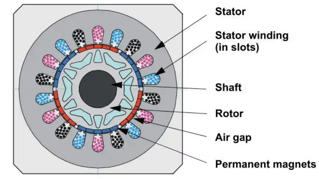
A Brushless DC Motor is a permanent magnet synchronous motor driven by an electronic controller instead of mechanical brushes.
Unlike conventional brushed DC motors, electrical commutation is performed electronically. The controller continuously energizes different stator windings according to the rotor position, generating a rotating magnetic field that keeps the rotor spinning.
Because there are no brushes or mechanical commutators, BLDC motors offer several important advantages:
- Higher efficiency
- Longer service life
- Lower maintenance
- Lower operating noise
- Higher power density
- Better speed regulation
Many modern products require motor performance beyond standard catalog models. In these situations, working with a custom BLDC motor manufacturer allows engineers to optimize motor dimensions, torque, speed, efficiency, and thermal performance for specific requirements.
Main Components and Their Functions in a BLDC Motor
Before exploring the electromagnetic principles and electronic commutation, it is helpful to understand the BLDC Motor Structure and mechanical makeup of a BLDC motor. The following diagram illustrates the major components and how they are assembled into a complete motor.
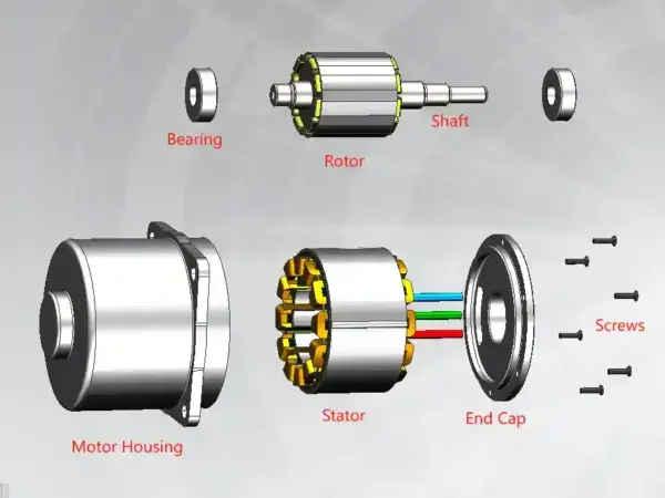
A BLDC motor is composed of multiple precision components assembled into a compact electromechanical system. Every component contributes to the motor’s mechanical strength, electromagnetic performance, and operational reliability.
A typical BLDC motor consists of the following major parts:
| Component | Main Function |
|---|---|
| Stator | Contains windings and generates the rotating magnetic field |
| Rotor | Contains permanent magnets and converts electromagnetic torque into rotation |
| Shaft & Bearings | Support rotor rotation and transmit mechanical torque |
| Housing | Provides mechanical protection, structural support and heat dissipation paths |
| End Cover / Flange | Supports bearings and maintains rotor-stator alignment |
| Position Sensor | Detects rotor position for sensored control systems |
| Controller | Controls phase current switching and electronic commutation |
For a detailed breakdown of BLDC motor construction, materials and manufacturing considerations, see our BLDC Motor Components Guide.
How Is a BLDC Motor Assembled?
Although different motor designs vary, the overall assembly process follows a similar sequence.
Typical Assembly Sequence
Motor Housing → Stator Press Fit → Rotor & Shaft Installation → Bearing Assembly → End Caps → Sensor / Lead Connection → Testing
Proper assembly helps maintain rotor alignment, air-gap consistency, low vibration and reliable motor performance.
Sensored vs Sensorless BLDC Control
| Sensored Control | Sensorless Control |
|---|---|
| Uses Hall sensors or encoder feedback | Estimates rotor position electrically |
| Reliable position information at low speed and startup | Reduces sensors, wiring and mechanical complexity |
| Useful where startup torque and position information matter | Common where cost, size and simplicity matter |
Key Difference:
Sensored systems measure rotor position directly, while sensorless systems estimate it from electrical signals such as back-EMF or observer-based algorithms.
How Does Electromagnetic Rotation Work?
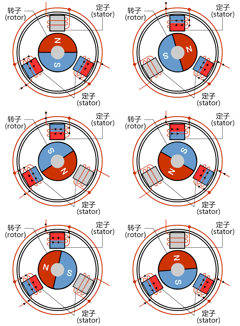
The BLDC motor working principle is based on electromagnetic interaction between the stator and the permanent-magnet rotor.
When current flows through a stator winding, it generates a magnetic field according to Ampere’s Law.
The controller energizes different stator phases sequentially.
Each energized phase creates a new magnetic field.
The rotor’s permanent magnets naturally attempt to align with this magnetic field.
As soon as alignment occurs, the controller switches current into another winding.
This repeating sequence creates continuous rotation without mechanical brushes.
The overall energy conversion process can be summarized as:
Phase Current → Stator Magnetic Field → Rotor–Stator Field Interaction → Electromagnetic Torque → Continuous Rotation
How Does a BLDC Motor Work Step by Step?
The complete BLDC motor working process can be summarized in six continuous steps:
Step 1 —Powered by Battery/DC power supply, the controller receives a speed or torque command.
↓
Step 2 —Rotor position is detected by Hall sensors, Encoders or estimated electronically via sensorless back‑EMF.
↓
Step 3 — The controller selects the appropriate commutation state. In typical six-step control, two motor phases are energized while the third phase remains unpowered.
↓
Step 4 — The energized stator windings create a magnetic field at the required electrical angle.
↓
Step 5 — Interaction between the stator magnetic field and the rotor’s permanent-magnet field produces electromagnetic torque.
↓
Step 6 — The controller continuously switches the energized phases, maintaining smooth and continuous rotation.
BLDC Motor Control Methods
Different control algorithms determine how current is supplied to the motor windings. Each method offers different trade-offs in efficiency, smoothness, complexity, and cost.
Six-Step Control
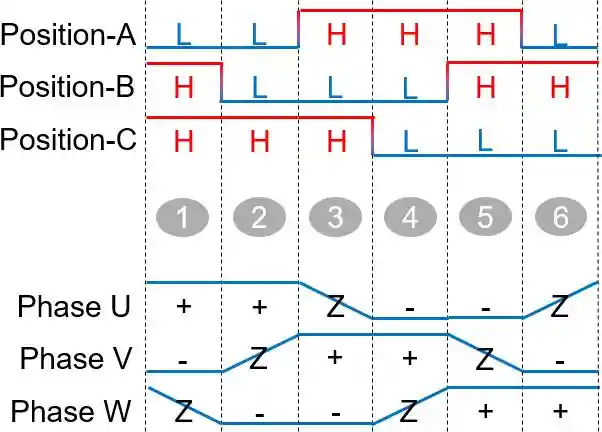
Six-step control, also known as trapezoidal commutation, energizes two motor phases at a time.
Every 60 electrical degrees, the controller switches to the next commutation state.
| Electrical Angle Range | Conducted Phases |
| 0° ~ 60° | U+ V- |
| 60° ~ 120° | U+ W- |
| 120° ~ 180° | V+ W- |
| 180° ~ 240° | V+ U- |
| 240° ~ 300° | W+ U- |
| 300° ~ 360° | W+ V- |
Advantages
- Simple implementation
- Low controller cost
- Fast response
- High starting torque
Limitations
- Noticeable torque ripple
- Higher vibration
- Higher acoustic noise
- Lower efficiency than advanced algorithms
Sinusoidal Control
Sinusoidal control gradually changes phase currents so that each winding receives a smooth sinusoidal waveform instead of abrupt switching.
Sinusoidal control drives the motor phases with smoothly varying current waveforms rather than abrupt six-step commutation. This can reduce torque ripple, vibration and acoustic noise, especially when the motor’s back-EMF and winding design are suited to sinusoidal excitation.
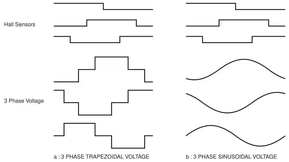
Compared with six-step control, sinusoidal control provides:
- Lower torque ripple
- Reduced vibration
- Lower operating noise
- Smoother rotation
However, it requires more complex control algorithms.
Field-Oriented Control (FOC)
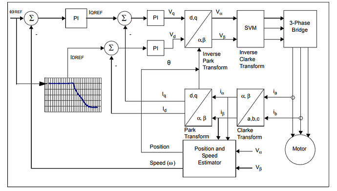
Field-Oriented Control (FOC) uses mathematical transformations to control torque-producing and flux-producing current components independently. This enables smooth torque control, good dynamic response and efficient operation across a wide operating range.
Advantages
- Smooth torque output
- Good low-speed control
- Reduced torque ripple
- Wide speed-control range
- High dynamic performance
FOC requires more computation, current sensing and controller complexity than six-step control, so the best control method depends on performance, cost and application requirements.
Frequently Asked Questions About BLDC Motors
How long can a BLDC motor operate?
A properly designed BLDC motor can provide a long service life because it has no brushes or mechanical commutator. Actual lifetime depends mainly on bearing life, winding temperature, insulation system, operating speed, load and environmental conditions.
Can a BLDC motor be customized for a specific application?
Yes. We can customize the motor’s torque, speed, voltage, dimensions, winding, thermal design, mechanical interface, and controller according to the application requirements.
Can the controller be integrated into a BLDC motor?
Yes. For many modern mechatronic products, we can integrate the controller, sensors, communication interface, and protection functions into the motor assembly. This can reduce wiring and installation space.
What causes a BLDC motor to become noisy or vibrate?
Common causes include electromagnetic torque ripple, rotor imbalance, bearing problems, air-gap variation, structural resonance, and inappropriate control parameters. Reducing noise usually requires both electromagnetic and mechanical optimization.
When should I consider a custom BLDC motor?
A custom BLDC motor is worth considering when a standard motor cannot meet requirements for torque, speed, efficiency, temperature rise, noise, dimensions, weight, reliability, or mechanical integration. In these cases, we can optimize the motor around the actual application rather than adapting the product to a catalog motor.
Conclusion
Now you understand how does a BLDC motor work.
A BLDC motor operates through the seamless integration of three engineering disciplines: mechanical structure, electromagnetic energy conversion, and electronic control. The stator generates a rotating magnetic field, the permanent-magnet rotor follows that field to produce torque, and the electronic controller continuously manages commutation to maintain smooth, efficient operation.
While the basic operating principle is straightforward, achieving high efficiency, low vibration, precise torque, and long‑term reliability depends on careful optimization of motor structure, electromagnetic design, and control algorithms — core components within the BLDC Motor Design Process. Knowing how does a BLDC motor work allows engineers to select suitable motor structures and control strategies for different applications.