Introduction
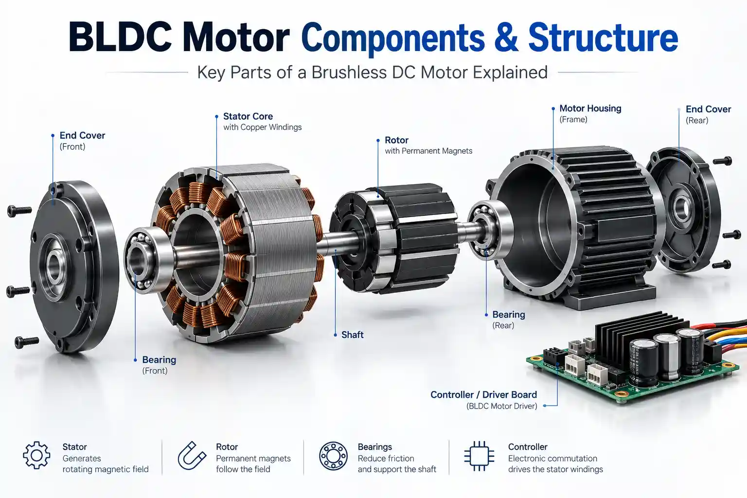
The main physical components of a BLDC motor include the stator, rotor, permanent magnets, shaft, bearings, housing and end covers. Electronic commutation is provided by a controller, which may be integrated with the motor or installed separately.
This guide explains the structure, materials and function of each major BLDC motor component, with diagrams and exploded views showing how the parts fit and work together.
The performance and reliability of a BLDC motor depend not only on voltage, speed and torque specifications, but also on the design, material selection, manufacturing quality and assembly accuracy of its internal components.
At Smart Drive, we develop custom BLDC motors around the actual application requirements, including size, torque, speed, operating environment and mechanical integration.
1. Main BLDC Motor Components and Structure
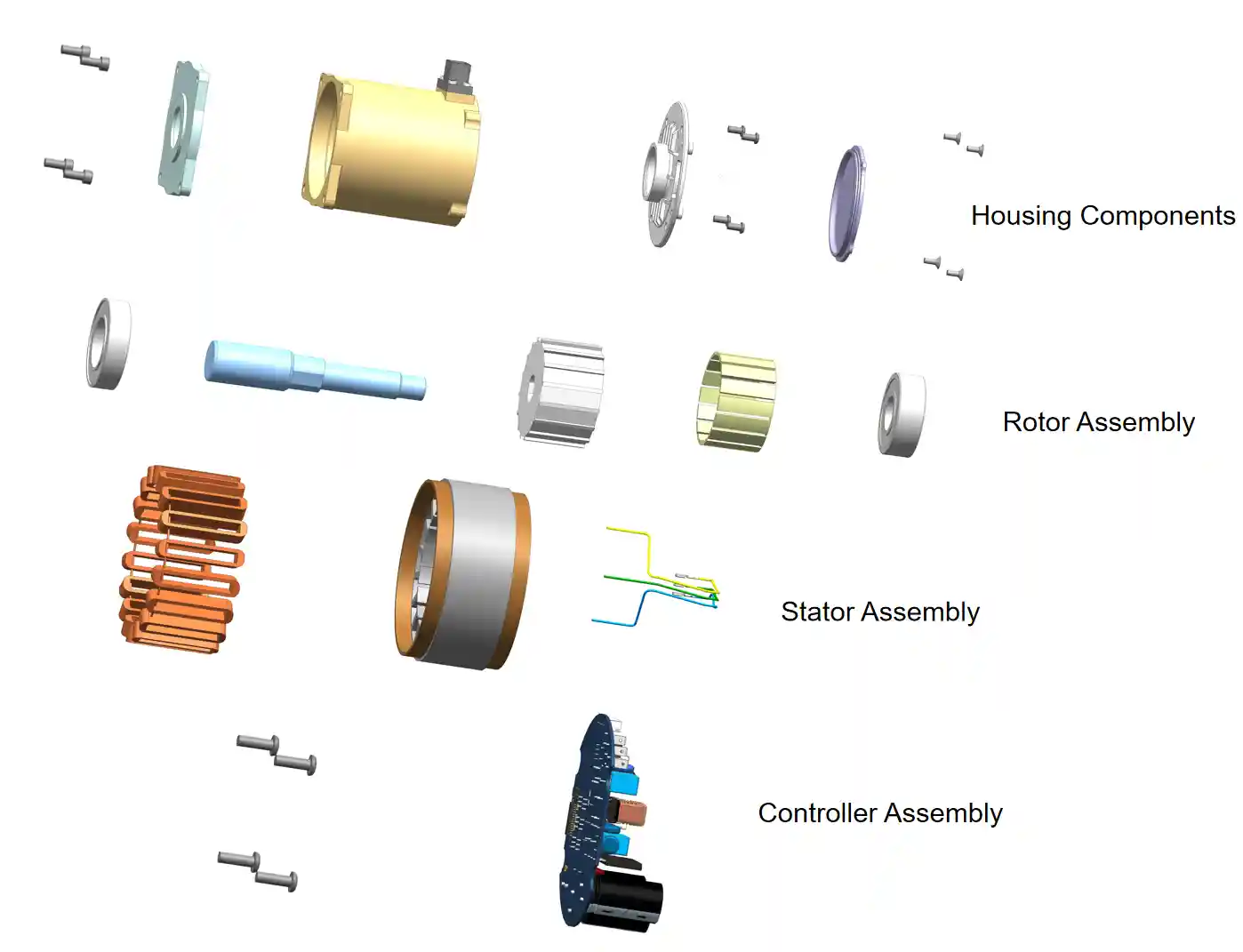
A typical BLDC motor can be divided into three main assemblies: the mechanical assembly, stator assembly and rotor assembly. Depending on the motor design, the electronic controller may be integrated into the motor or installed separately.
The complete motor structure normally includes:
| BLDC Motor Component | Main Function |
|---|---|
| Housing | Supports and protects internal components and helps transfer heat |
| Stator | Generates the rotating magnetic field |
| Rotor & Permanent Magnets | Interact with the stator magnetic field to produce torque |
| Shaft | Transfers mechanical torque to the load |
| Bearings | Support the rotor and maintain alignment |
| End Covers / Flange | Position bearings and provide mounting interfaces |
| Controller | Controller — Provides electronic commutation and motor control; may be integrated with the motor or installed separately |
The exact arrangement of these BLDC motor parts varies with motor topology, power level, speed, cooling method and application requirements.
2. Mechanical Assembly
The mechanical assembly provides structural support, alignment, torque transmission and rotating support for the motor. It also protects internal components and provides the mechanical interfaces required for installation and load connection.
Main mechanical components include:
- Motor housing
- End covers
- Mounting flange
- Shaft
- Bearings
- External mechanical interfaces
2.1 Motor Housing
The housing is one of the most important structural components.
Its main functions include:
- Fixing the stator assembly
- Protecting internal components
- Providing heat dissipation
- Maintaining mechanical strength
Aluminum Housing Materials
For medium and high-performance BLDC motors, aluminum alloys are commonly used.
Typical materials include:
Aluminum 6061
6061 aluminum alloy is widely used because of its balance between:
- Strength
- Lightweight
- Corrosion resistance
- Machining performance
Typical properties:
| Property | Value |
|---|---|
| Tensile strength | Around 310 MPa |
| Density | 2.7 g/cm³ |
| Thermal conductivity | About 167 W/m·K |
For CNC-machined motor housings, 6061-T6 aluminum is commonly used because of its strength, machinability and corrosion resistance. For high-volume die-cast housings, dedicated casting alloys such as ADC12 or A380 are more typical.
Applications:
- Industrial motors
- Robotics
- UAV motors
- Automotive actuators
Plastic Motor Housing
Small BLDC motors often use engineering plastics to reduce weight and cost.
Common materials:
Nylon + Glass Fiber (PA66+GF)
Advantages:
- High mechanical strength
- Good impact resistance
- Low weight
- Good electrical insulation
Typical applications:
- Small appliances
- Fans
- Pumps
- Consumer electronics
PPS + Glass Fiber
PPS (Polyphenylene Sulfide) is used for higher temperature applications.
Advantages:
- Excellent temperature resistance
- Chemical resistance
- Dimensional stability
Applications:
- Automotive motors
- High temperature pumps
- Precision equipment
Common processes:
- Injection molding
2.2 End Covers and Mounting Flange
The front and rear end covers have similar material requirements as the motor housing.
They mainly provide:
- Bearing positioning
- Shaft support
- Structural protection
- Mechanical mounting interface
The key requirement is machining accuracy because bearing alignment directly affects:
- Rotor concentricity
- Vibration
- Noise
- Motor lifetime
2.3 Shaft and Bearings
Motor Shaft
The shaft transfers torque from the rotor to the external load.
Common materials:
Stainless steel shafts, such as SUS304, may be selected when corrosion resistance is important, particularly in humid, outdoor or marine-related applications.
Medium-carbon steels such as 45 steel (similar to AISI 1045) are commonly used when higher strength, hardness and wear resistance are required.
Depending on the application, the shaft may be turned, ground and heat treated to achieve the required dimensional accuracy and mechanical properties.
Bearings
Bearings support rotor rotation and maintain the air gap between rotor and stator.
Common bearing solutions include:
- Deep-groove ball bearings for general BLDC motor applications
- Hybrid ceramic bearings for selected high-speed or low-friction applications
- Sleeve bearings for some low-load, cost-sensitive applications
Bearing selection depends on speed, radial and axial load, temperature, required life, lubrication and operating environment.
High-speed motors require bearings with:
- Low friction
- High precision
- Good thermal stability
3. Stator Assembly
The stator is the electromagnetic core of the motor.
If you want to understand how the stator generates a rotating magnetic field together with the rotor, read our How Does a BLDC Motor Work guide.
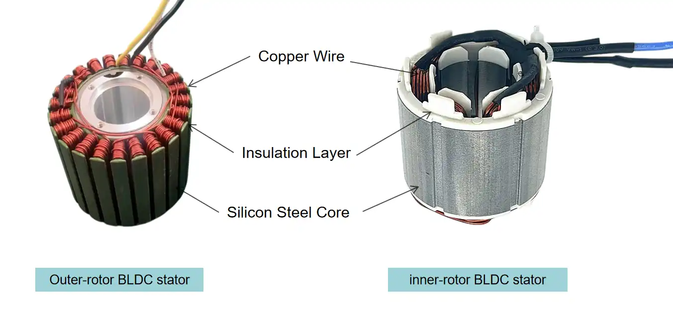
Main components:
- Silicon steel laminations
- Slot insulation
- Copper winding
- Insulation coating
3.1 Stator Core
The stator core is made from laminated electrical steel.
Silicon Steel Grades for Motor Cores:
| Grade | Thickness | P₁.₅/₅₀ (W/kg) | B₅₀ (T) | Typical Use |
|---|---|---|---|---|
| 50WW470 | 0.50 mm | ≤ 4.70 | 1.61 | Economy, low-speed motors |
| 50WW290 | 0.50 mm | ≤ 2.90 | 1.64 | Industrial servos, general BLDC |
| 35WW300 | 0.35 mm | ≤ 3.00 | 1.65 | Robot joints, drone motors |
| 35WW250 | 0.35 mm | ≤ 2.50 | 1.66 | High power-density, automotive |
Key Parameters
- Core Loss (P₁.₅/₅₀): Heat generated in the core per kilogram; lower value means cooler operation and higher efficiency. Critical for high-frequency / high-speed designs.
- Magnetic Induction (B₅₀): Flux density under 5000 A/m excitation; higher value delivers greater torque density within the same core volume.
- Lamination Thickness: Thinner sheets reduce eddy-current loss at high frequencies but raise material cost and stamping difficulty.
- Stacking Factor: Ratio of active magnetic material to total stack volume; typically 0.94–0.97, determined by insulation coating and lamination flatness.
The laminated structure reduces:
- Eddy current loss
- Heat generation
- Magnetic loss
Manufacturing process:
- Steel sheet stamping
- Lamination stacking
- Insulation coating
The quality of the stator core directly influences:
- Efficiency
- Torque density
- Temperature rise
For a deeper look at lamination grades and core manufacturing, see our Electrical Steel for BLDC Motors guide.
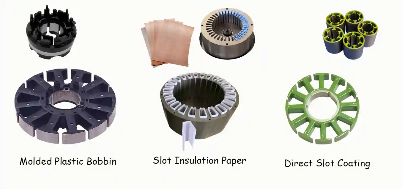
3.2 Slot & Bobbin Insulation of Stator Windings
Molded Plastic Bobbin
Structure: Injection-molded plastic frame fitted over stator teeth.
Insulation: Rigid integral barrier.
Material: GF-PBT, GF-PA66.
Pros: Friendly for automatic winding; Cons: Reduces slot fill factor.
Application: Small outer-rotor drone & miniature robot motors.
Slot Insulation Paper
Structure: Pre-cut flexible film inserted into slots.
Insulation: Soft lining layer on slot inner surfaces.
Material: PET, NMN, NHN.
Pros: Higher slot fill factor; Cons: Complicated insertion process.
Application: Robot joint motors, medium-sized industrial BLDC.
Direct Slot Coating
Structure: Insulating layer coated directly on slot walls.
Insulation: Thin in-situ dielectric film.
Material: Polyimide, epoxy coating.
Pros: Optimal slot utilization; Cons: Strict process control required.
Application: High-performance servo & hollow torque motors.
Learn more in our BLDC Stator Insulation guide.
3.3 Copper Windings
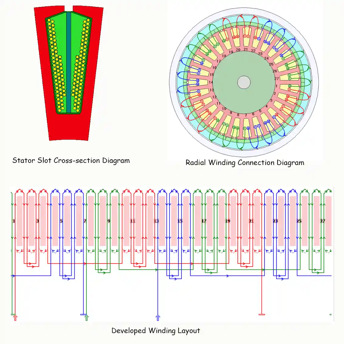
Copper winding generates the magnetic field required for motor operation.
Important parameters include:
- Wire diameter
- Number of turns
- Winding connection method: Delta or Star
- Slot fill factor
- Number of parallel branches
- Number of parallel strands
- Coil pitch
Manufacturing processes:
- Automatic winding
- Manual winding
- Forming
- Soldering
High-performance motors often require optimization of:
- Copper density
- Thermal path
- Winding arrangement
For winding materials, phase layout, manufacturing and testing, see our BLDC Motor Winding guide.
4. Rotor Assembly
The rotor is one of the most important components in a BLDC motor because it directly generates mechanical rotation through the interaction between permanent magnets and the stator magnetic field.
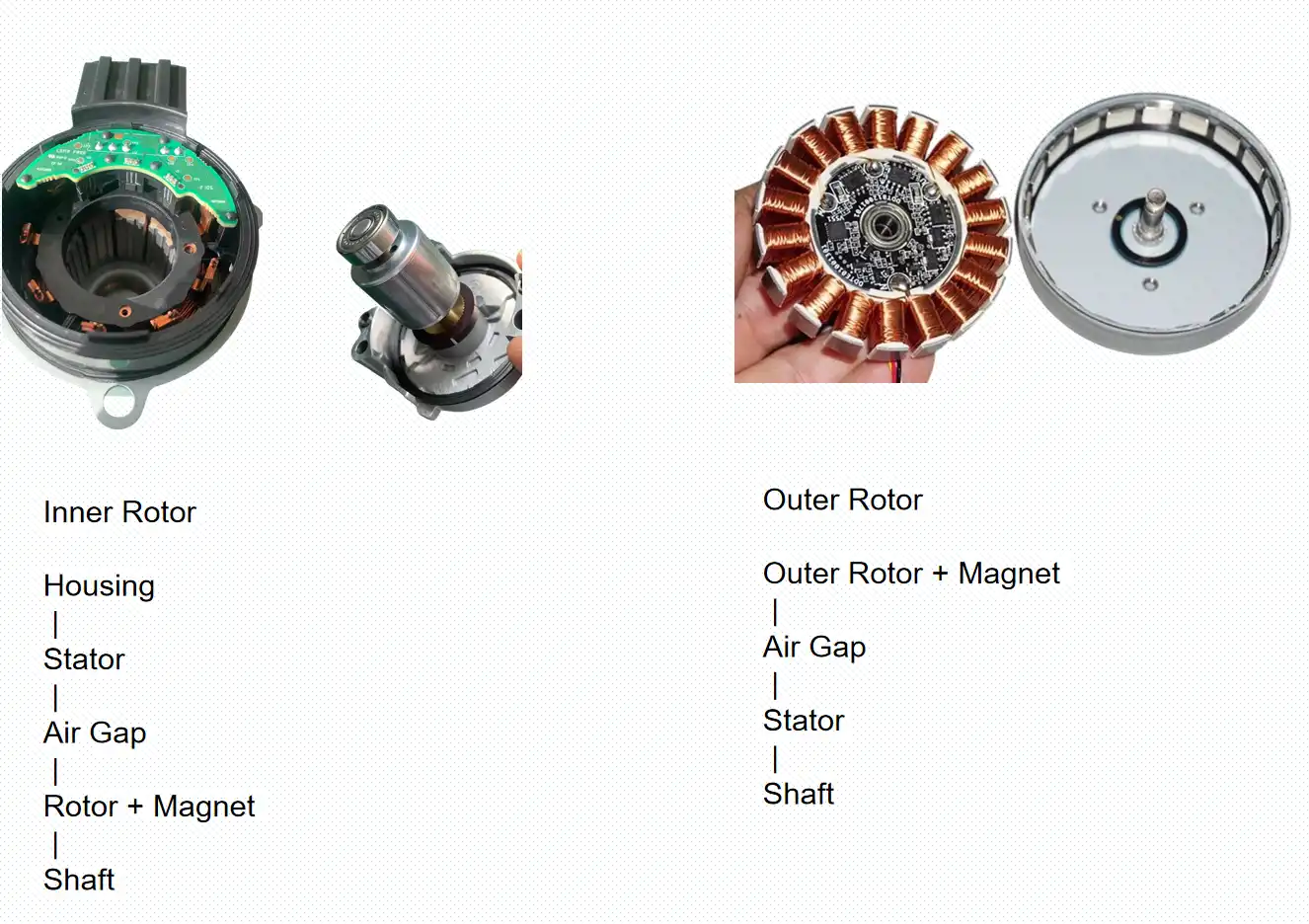
Based on the relative position between the rotor and stator, BLDC motors are mainly divided into two structural types:
- Inner Rotor BLDC Motor
- Outer Rotor BLDC Motor (Outrunner Motor)
The selection between these two structures depends on the required speed, torque, power density, mechanical integration, and application conditions.
Inner Rotor BLDC Motor Structure
In an inner rotor BLDC motor, the rotor is located inside the stator.
The stator is fixed to the motor housing, while the rotor with permanent magnets rotates together with the shaft inside the stator bore.
The typical structure is:
Motor Housing
|
|
Stator Core + Windings
|
Air Gap
|
Permanent Magnets
|
Rotor Core
|
Shaft
Inner rotor designs are widely used when high speed capability and compact mechanical dimensions are required.
Typical applications include:
- Industrial equipment
- Pumps
- Fans
- Automotive auxiliary motors
- Power tools
- Precision motion systems
Outer Rotor BLDC Motor Structure (Outrunner Motor)
In an outer rotor BLDC motor, the rotor is located outside the stator.
The stator remains fixed at the center, while the outer rotor containing permanent magnets rotates around the stator.
The typical structure is:
Outer Rotor Housing
|
Permanent Magnets
|
Air Gap
|
Stator Core + Windings
|
Motor Shaft
Outer rotor motors are commonly selected when high torque density and direct-drive capability are important.
Typical applications include:
- UAV and drone propulsion motors
- Electric fans
- Robotics joints
- Electric bicycles
- Marine thrusters
Rotor structure also influences torque-speed characteristics, which is an important factor when engineers select a BLDC motor for a new product.
4.1 Rotor Core
For laminated inner-rotor and IPM designs, the rotor core is typically manufactured from electrical steel laminations to provide the required magnetic path while limiting eddy-current losses. Outer-rotor motors may use a different rotor shell or magnetic return structure depending on the motor topology.
Rotor design must also consider mechanical strength, balance, magnet retention and maximum operating speed.
4.2 Permanent Magnets
Permanent magnets generate the rotor magnetic field and have a major influence on torque density, efficiency, operating temperature and rotor mechanical design.
4.2.1 Magnet Structure
BLDC rotors mainly use two permanent-magnet arrangements:
SPM (Surface Permanent Magnet)
Magnets are bonded to the rotor surface. SPM structures are relatively simple to manufacture, offer smooth magnetic performance and are widely used in pumps, fans, UAV motors and general-purpose BLDC motors.
IPM (Interior Permanent Magnet)
Magnets are embedded inside the rotor core. IPM structures provide stronger mechanical retention and can support wider speed ranges and higher-performance applications, but require more complex rotor design and manufacturing.
For outer-rotor BLDC motors, surface-mounted magnets are most common. Arc-segment magnets provide better conformity to the rotor shell, while rectangular magnets can reduce material and manufacturing cost.
4.2.2 Common Magnet Materials
| Magnet Material | Main Characteristics | Typical Applications |
|---|---|---|
| Sintered NdFeB | High magnetic strength and compact size | Most high-performance BLDC motors |
| High-temperature NdFeB | Improved resistance to thermal demagnetization | Automotive and high-load motors |
| Bonded NdFeB | Flexible shaping and good dimensional consistency | Small precision motors |
| Ferrite | Low cost and good corrosion resistance | Fans, pumps and cost-sensitive applications |
| SmCo | Excellent high-temperature stability | Aerospace and extreme-temperature applications |
The correct magnet grade should be selected according to the actual operating temperature, demagnetizing field, magnetic circuit and required torque density.
4.2.3 Mechanical and Thermal Considerations
Permanent-magnet design must also consider rotor speed, centrifugal force, adhesive strength, corrosion protection and temperature.
High-speed SPM rotors may require additional magnet-retention measures such as metallic sleeves or carbon-fiber overwraps. IPM structures provide inherent magnet retention, but high-speed rotor integrity still requires dedicated mechanical analysis.
For high-temperature applications, higher-coercivity NdFeB grades or SmCo magnets may be required to reduce the risk of irreversible demagnetization.
In practice, magnet selection should be evaluated together with rotor structure, target speed, torque, operating temperature, NVH requirements and manufacturing cost.

5. BLDC Motor Controller and Electronic Commutation
A BLDC motor requires electronic commutation, but the controller is not always physically integrated into the motor. Depending on the application, it may be mounted inside the motor housing, attached to the motor, or installed separately in the system.
The controller manages power switching, commutation and motor control. Rotor position information may be obtained through Hall sensors, encoders or other position sensors, or estimated using sensorless control methods depending on the design. Protection and communication functions may also be included according to the application requirements.
A typical controller may include:
- Power stage
- Control circuit / MCU
- Current and voltage sensing
- Optional position-feedback interface
- Optional communication interface
5.1 Main Hardware Components
MCU (Microcontroller)
The MCU is the controller’s processing unit. It manages PWM output, current sampling, fault detection, and communication with the host system.
Common suppliers include STMicroelectronics, Infineon, NXP, and Texas Instruments.
Power Stage
MOSFETs are widely used in low- and medium-voltage BLDC drives. At higher voltage or power levels, IGBTs or SiC MOSFETs may be selected depending on switching frequency, efficiency, cost and thermal requirements.
Typical components include:
- MOSFET bridge
- Gate driver IC
- Current sensing circuit
- DC bus capacitor
Rotor position information may be obtained using:
- Hall sensors
- Magnetic angle sensors
- Encoders
- Sensorless back-EMF estimation
The selected method depends on the required accuracy, speed, and application.
5.2 Controller Installation
Integrated controllers are commonly mounted inside the rear end cap or directly on the motor housing.
Internally, the controller connects to the stator through the U, V, and W phase terminals. External connectors provide power input, control signals, and communication.

Typical external interfaces include:
- DC power
- Hall sensor
- Encoder
- CAN Bus
- UART
- PWM control
5.3 Protection and Thermal Management
For demanding environments, the controller usually incorporates additional protection.
Conformal Coating
Acrylic, silicone, or polyurethane coatings are applied to the PCB to improve moisture, dust, and corrosion resistance.
Potting
For higher protection levels, the controller is encapsulated with epoxy, silicone, or polyurethane resin.
Potting provides:
- Vibration resistance
- Electrical insulation
- Improved durability
It is widely used in automotive pumps, outdoor equipment, and marine motors.
Thermal Management
Power devices generate significant heat during operation.
Common cooling solutions include:
- Aluminum heat sink
- Die-cast aluminum end cover
- Thermal pads
- Thermal grease
- Metal-core PCB (MCPCB)
Efficient heat transfer improves controller reliability and supports continuous high-load operation.
6. How BLDC Motor Components Come Together in Assembly
The performance of a BLDC motor depends not only on component quality but also on the precision of the assembly process. Dimensional accuracy, insulation quality, bearing alignment, and rotor balance all directly influence efficiency, noise, vibration, and service life.
A typical assembly process consists of four stages:
- Stator Assembly
- Rotor Assembly
- Controller Assembly
- Final Motor Assembly
6.1 Stator Assembly
The stator is assembled before it is installed into the motor housing.
Typical process:
Lamination Stacking
↓
Insulation Installation
↓
Coil Winding
↓
Lead Connection
↓
Impregnation / Potting if required
↓
Electrical Inspection
↓
Finished Stator Assembly
Key Process Requirements
- Core stacking should minimize burrs and maintain overall flatness.
- Slot insulation must completely isolate the winding from the steel laminations.
- Copper winding should maintain consistent turns, wire tension, and fill factor.
- When used, varnish impregnation (dip or vacuum pressure impregnation, VPI) can improve insulation strength, heat transfer and vibration resistance.
- After curing, the stator should pass insulation resistance and dielectric withstand tests before assembly.
6.2 Rotor Assembly
The rotor assembly combines the shaft, rotor core, and permanent magnets into a high-precision rotating unit.
Typical process:
Rotor Core
↓
Press-fit Shaft
↓
Magnet Bonding
↓
Retaining Sleeve (Optional)
↓
Dynamic Balancing
↓
Finished Rotor Assembly
Key Process Requirements
- The shaft must be accurately press-fitted to maintain concentricity.
- Permanent magnets are bonded using high-strength structural adhesive and must be positioned with the correct magnetic polarity.
- High-speed rotors may require a carbon fiber or stainless-steel retaining sleeve to prevent magnet separation caused by centrifugal force.
- Dynamic balancing (typically ISO 21940) minimizes vibration and improves bearing life.
6.3 Final Motor Assembly
After the stator and rotor assemblies are completed, they are integrated into the final motor.
Typical process:
Housing Preparation
↓
Press-fit Stator
↓
Install Bearings
↓
Insert Rotor Assembly
↓
Install End Caps
↓
Mount Controller (if integrated)
↓
Connect Motor Leads / U-V-W Phases
↓
Electrical & Mechanical Testing
Key Process Requirements
Stator Installation
The stator is usually press-fitted into the housing to ensure good mechanical rigidity and efficient heat transfer.
Bearing Installation
Bearings should be pressed onto the correct race using dedicated tools to avoid preload or damage.
Rotor Installation
The rotor must rotate freely without contacting the stator. The designed air gap should remain uniform around the full circumference.
Controller Connection
For motors with an integrated controller, the controller is connected to the stator through the U, V, and W phase terminals, followed by the required sensor, power and communication connections. For systems using an external controller, motor phase leads and sensor interfaces are routed to the external connector instead.
Performance Testing
Typical final inspection and functional testing may include:
- No-load speed
- Phase resistance
- Insulation resistance
- High-voltage withstand
- Current consumption
- Noise and vibration
- Rotation direction
- Functional test
For a complete explanation of inspection, torque-speed performance, thermal validation, reliability and application-level testing, see our BLDC Motor Testing Guide.
7. How Component Choices Change in Custom BLDC Motor Design
In a custom BLDC motor project, component selection cannot be separated from the application requirements. Housing material, shaft geometry, bearing type, stator structure, winding specification, rotor topology and magnet grade are selected together according to the required torque, speed, voltage, size, environment and production volume.
Smart Drive supports this process from motor design and prototyping through validation and manufacturing.
Our engineering capability includes:
Mechanical Design
- Housing optimization
- Shaft design
- Bearing selection
- Structural integration
Electromagnetic Design
- Stator optimization
- Rotor magnetic design
- Performance simulation
Prototype Development
- Rapid prototype production
- Functional testing
- Design validation
Low Volume Manufacturing
- Pilot production
- Engineering modification
- OEM manufacturing support
8. Frequently Asked Questions About BLDC Motor Components
8.1 What are the main components of a BLDC motor?
The main components typically include the stator, rotor, permanent magnets, shaft, bearings, housing and end covers. A controller is also required for electronic commutation, although it may be integrated into the motor or installed separately.
8.2 What is the difference between the stator and rotor in a BLDC motor?
The stator remains stationary and carries the windings that generate the rotating magnetic field. The rotor rotates in response to this field and transfers mechanical torque through the shaft.
8.3 What does a BLDC motor exploded view show?
A BLDC motor exploded view shows how major parts such as the housing, end covers, bearings, shaft, rotor, magnets, stator and controller interface are positioned and assembled.
Conclusion
A BLDC motor combines mechanical, electromagnetic and electronic elements into one operating system. Its main components—including the housing, bearings, shaft, stator, rotor, permanent magnets and controller interface—must work together to achieve the required torque, speed, efficiency, thermal performance and reliability.
Understanding the parts and structure of a BLDC motor helps engineers evaluate design choices, identify potential failure points and define more suitable specifications for a new application.
Smart Drive supports custom BLDC motor projects from structure and electromagnetic design through prototyping, testing and production.